System and methods of tracking using radio frequency identification

a technology of radio frequency identification and tracking method, which is applied in the direction of visible signalling system, electric/electromagnetic visible signalling, instruments, etc., can solve the problems of affecting the signal strength reading, difficult to determine on which side of the wall an rfid tag is located, and may not be preferred in indoor environments, so as to reduce the risk of emf exposure, reduce processing resources, and increase accuracy

Inactive Publication Date: 2015-12-31
TECHIP INT
View PDF14 Cites 26 Cited by
  • Summary
  • Abstract
  • Description
  • Claims
  • Application Information

AI Technical Summary

Benefits of technology

[0017]Second, zone indicators may even use overlapping areas of coverage due to the indicators not always being “on.” Thus, for example, additional low frequency RFID receivers / exciters can be placed in overlapping zones. This can lead to increased accuracy and / or decreased processing resources needed for determining the location and / or movement path of a particular asset (and its associated RFID tag) within a facility.
[0018]Third, zone indicators may be placed into a nominally “off” or sleep mode with little or no EMF emissions—unless triggered to a temporary “on” state. The selective activation of a given zone indicator leads to 1) a total reduction in EMF exposure risk for those within a given facility; 2) a total reduction in data traffic (e.g., over wired or wireless connections) because of decreased quantity of data being transmitted (e.g., from a zone indicator, its controller, and / or the RFID tag); and / or 3) reduced load on backend servers that perform data processing associated with the data traffic.
[0019]Fourth, in certain examples, the tag location information provided by the augmented presence indicators may itself also provide trajectory and speed information (e.g., via a laser range finder). This additional information can be used to decrease processing resources (e.g., at backend servers) needed for determining where a particular tagged asset is headed. For example, the need to “guess” or “smooth” obtained trajectory information can be eliminated or decreased. Additional presence and / or trajectory information can be used to provide real-time actual information and / or to provide an instant replay capability.
[0020]In certain examples, improved accuracy can be achieved for tag location information by the addition of new data sets per tag that include trajectory and speed of the asset (or tag associated with the asset).
[0021]Certain example embodiments may also provide increased security. For example, when a sensor of a zone indicator is activated and no corresponding tag data is received (e.g., in response to being excited) the system may assume that the detected object is without a tag. An alert (e.g., a page, e-mail, text, alarm, etc.) can then be issued or logged based on the detection of such occurrences. This can lead to increased safety and / or security for a facility.

Problems solved by technology

However, such triangulation techniques may not be preferred in indoor environments due to the presence of walls, partitions, or other barriers that physically separate portions of a facility without necessarily separating the RF signals emitted from receivers, tags, and / or multi-path signal artifacts (e.g., caused by at least partial absorption or reflections of such RF signals).
But due to the physical proximity of the readers it may be difficult to determine on which side of the wall an RFID tag is located.
Further, movement of doors, persons, or the like within a room may affect the signal strength readings.
This technique, however, may have downsides as well.
Given the typically complex layout of these and other facilities (e.g., multiple entrances per corridor, multiple elevator banks, etc.), the installation and setup process per zone indicator can be complex and time consuming.
Moreover, there is still a chance that a tag close to a wall in room ‘A’ will be incorrectly “detected” as being in the zone of Room ‘B’.
Also, in certain environments, zone indicators can overlap and result in an inaccurate or lost RFID tag location.
For example, overlapping low-frequency RF signals may destructively combine to at least partially “destroy” each other—thus rendering tags that enter these “dead-zone” areas with an unknown or wrong location.
While electromagnetic emissions from a single low-frequency RF transmitter (or other exciter / receiver / transmitter) may be well under a possibly harmful range, a facility with tens or hundreds of continually emitting zone indicators may have a cumulative effect.
Another potential issue is that the volume of data messaging between tags, zone indicators, and a central system can exponentially increase when additional zone indicators are introduced into the typical prior art system (e.g., to increase accuracy, cover additional rooms, etc.).
However, until the tag enters a new zone (i.e., progresses from a first zone to a second zone) no concrete directional information may be provided.
However, the processing involved can be computationally expensive (and still prone to error due to the nature of considerable “guesswork” involved)—and even then only providing an indication for large increments of tag movement.
Second, zone indicators may even use overlapping areas of coverage due to the indicators not always being “on.” Thus, for example, additional low frequency RFID receivers / exciters can be placed in overlapping zones.
This can lead to increased accuracy and / or decreased processing resources needed for determining the location and / or movement path of a particular asset (and its associated RFID tag) within a facility.

Method used


Image

  • System and methods of tracking using radio frequency identification
  • System and methods of tracking using radio frequency identification
  • System and methods of tracking using radio frequency identification

Examples


Embodiment Construction

[0042]The following description is provided in relation to several example embodiments that may share common characteristics and / or features. It is to be understood that one or more features of any of the embodiments may be combinable with one or more features of other example embodiments. In addition, any single feature or combination of features in any of the embodiments may constitute an additional embodiment. As used herein, the term “or” is meant to be inclusive (e.g., either A or B individually, or both A and B together) rather than exclusive (e.g., A or B, but not both).

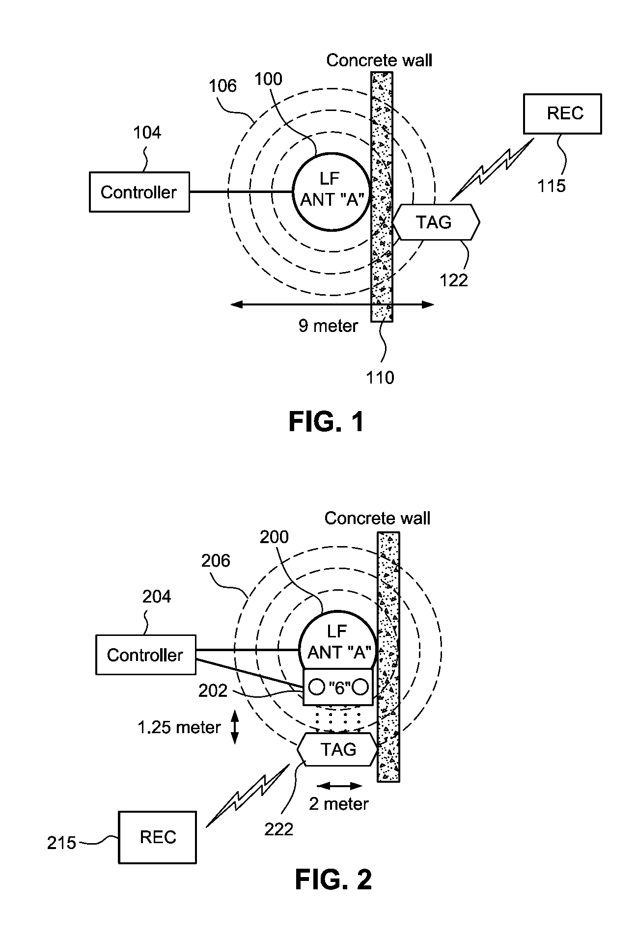
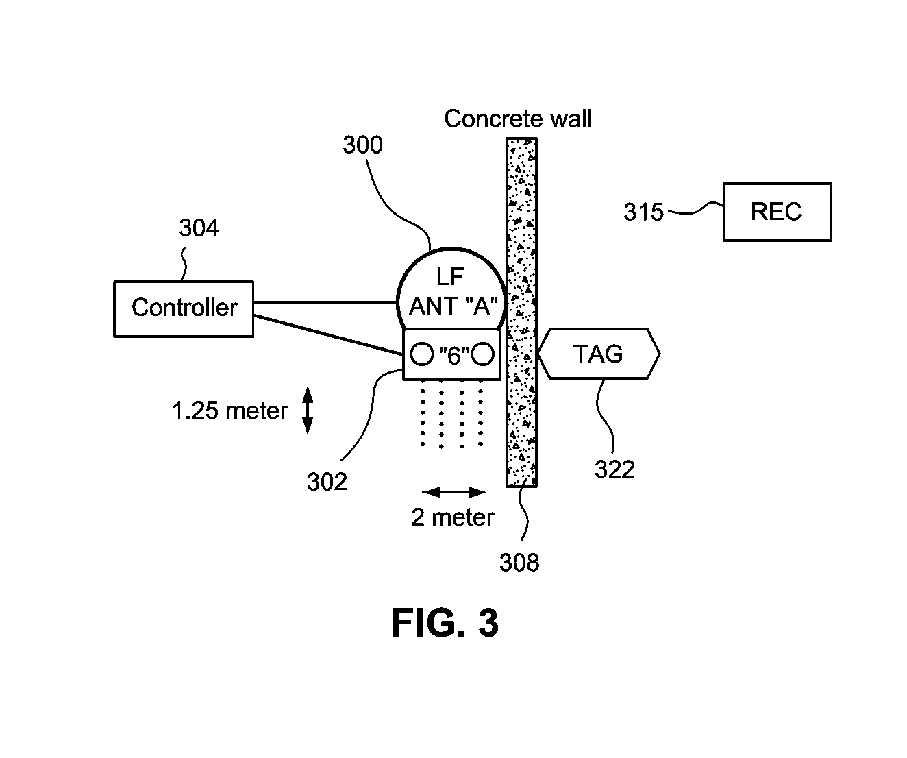
[0043]Certain example embodiments herein may relate to systems and methods of tracking (e.g., in real-time) the position of an asset using radio frequency identification (RFID). In certain example embodiments, RTLS (real time location services) and RFID (radio frequency identification) are used to determine the location of a RFID tag. When the tag is in an area with an active electromagnetic radio frequency tr...


PUM


Abstract

A system for tracking movement of assets or persons includes a presence sensor coupled to an RFID exciter or transmitter. Upon detection of object presence by a sensor, the exciter is turned on and caused to transmit an RFID tag exciting signal. The signal may be received by and activate a corresponding RFID tag that is within range of the exciter. The RFID tag may then transmit its ID, the ID of the exciter, and the sensed presence information to a remote RF receiver and back-end data processing system.

Description

CROSS-REFERENCE TO RELATED APPLICATIONS[0001]This application claims priority to U.S. Provisional Application No. 62 / 018,485, filed Jun. 27, 2014, the contents of which are hereby incorporated by reference in its entirety.FIELD[0002]The technology herein generally relates to movement or location tracking (e.g., in real-time) of assets or people by using radio frequency identification devices.BACKGROUND AND SUMMARY[0003]Radio frequency identification (RFID) relates to tracking, identifying, or otherwise interrogating electronic “tags” using radio frequency (RF) electromagnetic fields to power on-board electrical circuits and / or to provide one or more RF communication channels. Generally speaking, an electronic RFID tag (e.g., a “RFID tag” or “tag”) includes an electronic circuit to process and store information and an RF antenna or transceiver to send and / or receive information via electromagnetic signals of at least one frequency.[0004]RFID tags may be further broken down into vario...

Claims


Application Information

Patent Timeline
Patent Type & Authority Applications(United States)
IPC IPC(8): G08B25/10
CPCG08B25/10G06Q10/0833G08B21/0275
Inventor VARDI, EYAL DOV
Owner TECHIP INT
Why Eureka
Try Eureka