
Method of manufacturing thermoelectric conversion material

a manufacturing method and thermoelectric technology, applied in the direction of electric furnaces, furnace types, furnaces, etc., can solve the problems of low seebeck coefficient s, inability to form uniform crystals, and conventional manufacturing methods, and achieve the effect of high seebeck coefficien

Inactive Publication Date: 2015-12-31
PANASONIC CORP
View PDF3 Cites 11 Cited by
  • Summary
  • Abstract
  • Description
  • Claims
  • Application Information

AI Technical Summary

Benefits of technology

The patent text describes a reliable method for making a thermoelectric material called X3Ni3Sb4. This method can produce a high-quality material with good performance. The method involves using specific elements and ratios to create the desired material. This technique can be used to manufacture various thermoelectric materials with high efficiency.

Problems solved by technology

A sample formed by a conventional manufacturing method has a low Seebeck coefficient S and cannot form uniform crystals.

Method used


Image

  • Method of manufacturing thermoelectric conversion material
  • Method of manufacturing thermoelectric conversion material
  • Method of manufacturing thermoelectric conversion material

Examples


first embodiment

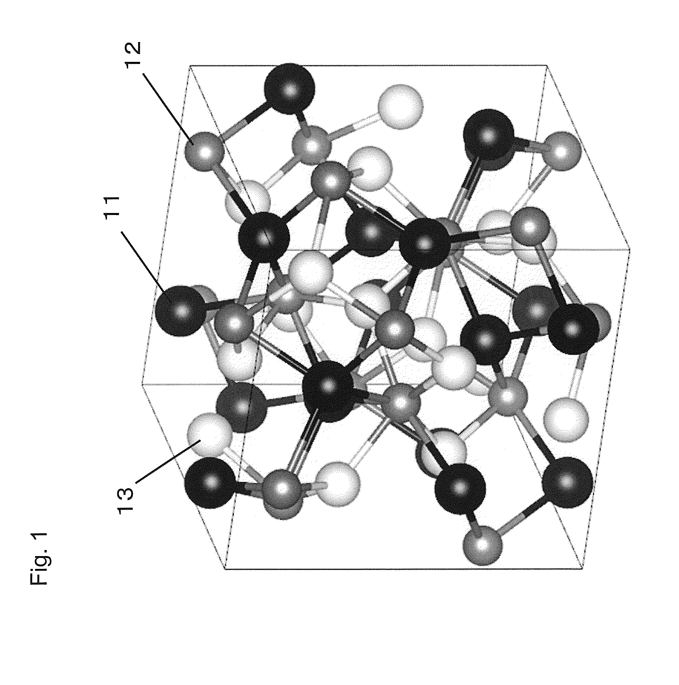
[0034]Description will be made of a method of manufacturing the thermoelectric conversion material X3T3Z4 (X is composed of one or more elements selected from Zr, Hf, Y, La, Nb, and Ta, while including at least Zr or Hf; T is composed of one or more elements selected from Ni, Co, Cu, Rh, Pd, Ir, and Pt, while including at least Ni; Z is composed of one or more elements selected from Sb, Ge, and Sn, while including at least Sb) according to a first embodiment of this disclosure. The compound X3T3Z4 is a thermoelectric conversion material and has symmetry of a cubic crystal belonging to a space group I-43d. FIG. 1 is a schematic of a crystal structure of the thermoelectric conversion material X3T3Z4. As depicted in FIG. 1, the thermoelectric conversion material X3T3Z4 has the crystal structure in which atoms are arranged at a ratio of X:T:Z=3:3:4 in a unit cell.

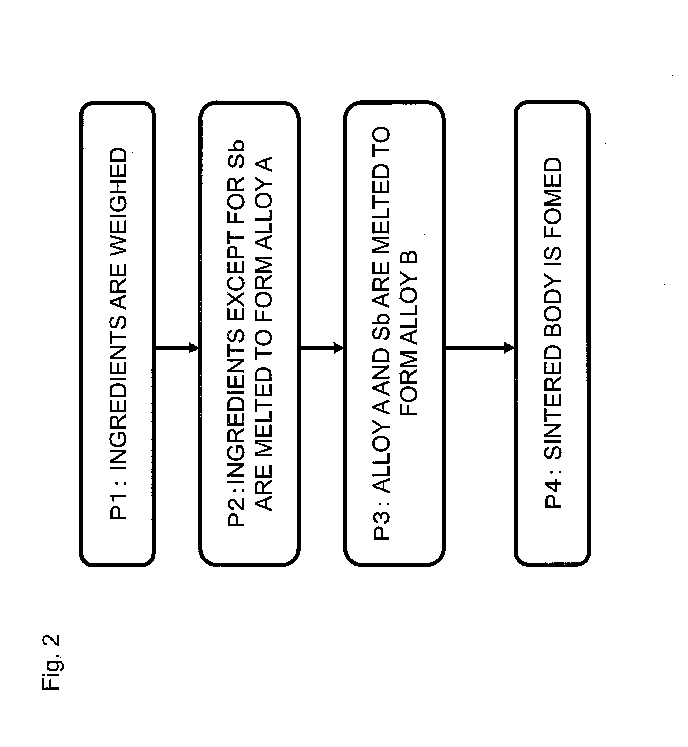
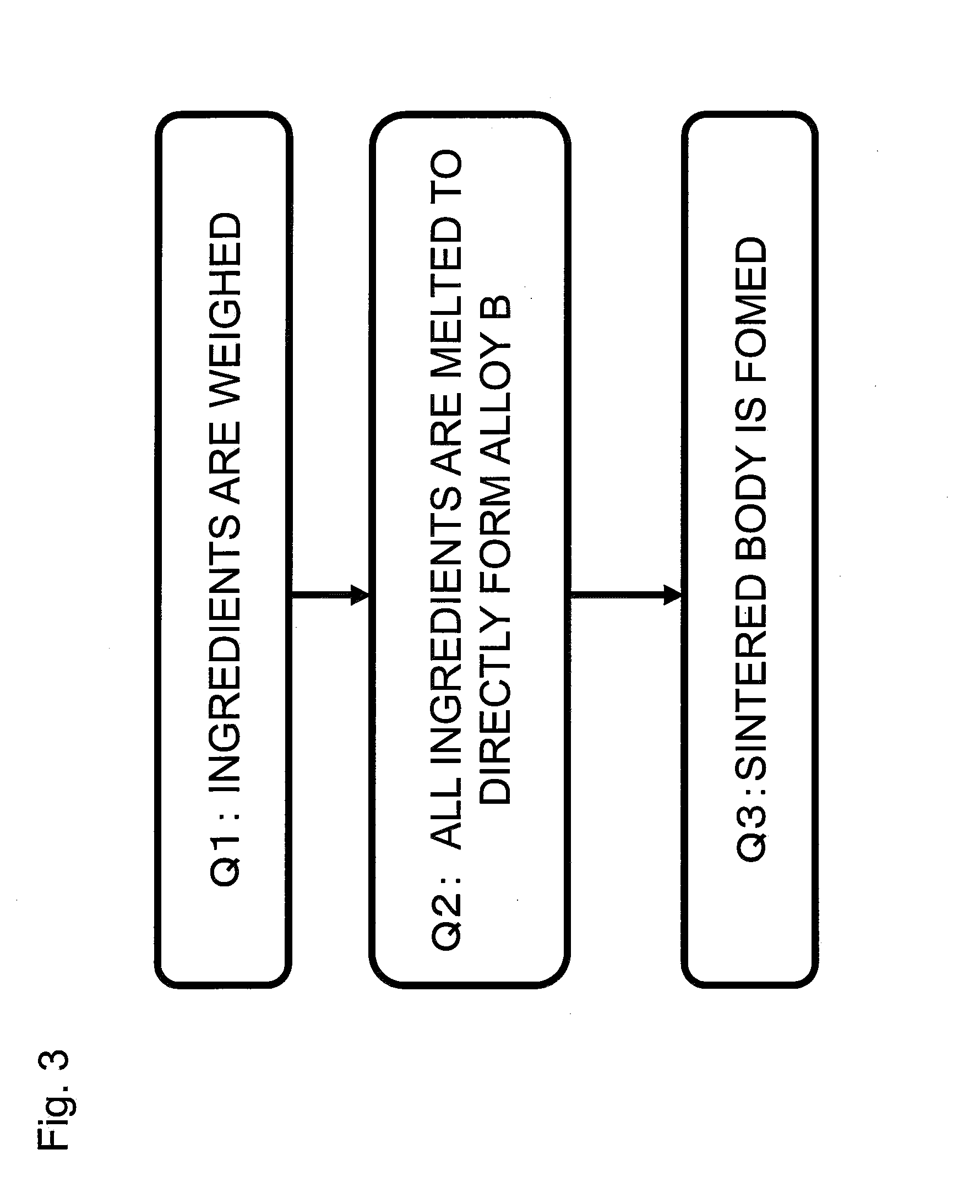
[0035]FIG. 2 is a flowchart of processes of the method of manufacturing a thermoelectric conversion material according to the...

example 1

[0040]A sintered body was formed by the manufacturing method described in the first embodiment from the compound X3T3Z4 (X is composed of one or more elements selected from Zr, Hf, Y, La, Nb, and Ta, while including at least Zr or Hf; T is composed of one or more elements selected from Ni, Co, Cu, Rh, Pd, Ir, and Pt, while including at least Ni; Z is composed of one or more elements selected from Sb, Ge, and Sn, while including at least Sb).

[0041]A specific manufacturing method will first be described.

[0042](a) Zr, Hf, Y, La, Nb, Ta, Ni, Co, Cu, Rh, Pd, Ir, Pt, Sn, Ge, and Sb used as ingredients were weighed to a stoichiometric ratio of Zr+Hf+Y+La+Nb+Ta:Ni+Co+Cu+Rh+Pd+Ir+Pt:Ge+Sn+Sb=3:3:4 (process P1). A composition ratio estimated from the weighed ingredients is referred to as preparation composition.

[0043](b) Among the weighed ingredients, the ingredients except Sb (materials containing desired elements selected from Zr, Hf, Y, La, Nb, Ta, Ni, Co, Cu, Rh, Pd, Ir, Pt, Ge, and Sn) w...


PUM

PropertyMeasurementUnit
temperatureaaaaaaaaaa
inner diameteraaaaaaaaaa

Abstract

A method of manufacturing a thermoelectric conversion material expressed by a chemical formula X3T3Z4 (X comprises one or more elements selected from Zr, Hf, Y, La, Nb, and Ta, while including at least Zr or Hf; T comprises one or more elements selected from Ni, Co, Cu, Rh, Pd, Ir, and Pt, while including at least Ni; Z comprises one or more elements selected from Sb, Ge, and Sn, while including at least Sb), the method comprising: preparing materials containing elements, which are the X including selected elements, the T including selected elements, and the Z including selected elements; forming an alloy A by melting the materials containing the all selected elements except for Sb; and forming an alloy B by melting the alloy A and the material containing Sb.

Description

CROSS-REFERENCE TO RELATED APPLICATIONS[0001]This is a continuation application of International Application No. PCT / JP2014 / 001883, with an international filing date of Mar. 31, 2014, which claims priority of Japanese Patent Application No. 2013-82363 filed on Apr. 10, 2013, the contents of which is incorporated herein by reference.BACKGROUND OF THE INVENTION[0002](1) Field of the Invention[0003]This disclosure relates to a method of manufacturing a thermoelectric conversion material utilized for thermoelectric power generation and thermoelectric cooling.[0004](2) Description of Related Art[0005]The thermoelectric power generation is a technology of converting thermal energy directly into electric energy by utilizing the Seebeck effect i.e., thermoelectromotive force generated between both ends of a substance by a temperature difference made between the both ends of the substance in proportion to the temperature difference. This technology is practically used as a power source for a...

Claims


Application Information

Patent Timeline
Patent Type & Authority Applications(United States)
IPC IPC(8): H01L35/20C22C1/04C22C30/04C22C30/00C22C30/02C22C1/02C22C12/00
CPCC22C12/00C22C1/02C22C30/00H01L35/18C22C1/0491C22C1/04C22C30/02C22C30/04H01L35/20C22C1/047H10N10/853H10N10/854
Inventor TAMAKI, HIROMASAKANNO, TSUTOMUSAKAI, AKIHIROTAKAHASHI, KOHEIKUSADA, HIDEOYAMADA, YUKA
Owner PANASONIC CORP
Learn More