
Encryption System in a Virtualized Environment

Pending Publication Date: 2015-12-31
NICIRA
View PDF17 Cites 16 Cited by
  • Summary
  • Abstract
  • Description
  • Claims
  • Application Information

AI Technical Summary

Benefits of technology

The described hypervisor-based encryption scheme combines the benefits of in-guest encryption and network-based encryption. It optimizes key management for multiple virtual machines and enforces fine-grained encryption policies. This results in a context-aware, hypervisor-based network encryption solution that achieves both isolation between the encryption and the virtual machine operations, as well as efficient and effective encryption.

Problems solved by technology

Overlay networks provide the same service across the wide area network (WAN) on a public network for enterprises, and are susceptible to threats such as snooping, man in the middle attack (MITM), and forging.
The privacy guarantee of private datacenters is no longer assumed, and threats similar to those in the Internet prevail.
However, current approaches to encrypt network data fall short in terms of contextual information, isolation, granularity, or ease of management.
However, IPSec tunneling by the edge devices is oblivious to the application context and the user generating the network traffic, lacks granularity as it encrypts data in bulk, and cannot address various internal threats as the traffic between the virtual machines (VMs) and the edge devices is in plaintext.
Moreover, the known problem with traditional IPSec is that both endpoints negotiate a security association, and agree upon a key.
However, in-guest encryption fails to isolate the protected data from the protection mechanism as they both reside in the guest.
This scheme also suffers from inability for upgrades, and is extremely difficult to manage from a centralized management console.

Method used


Image

  • Encryption System in a Virtualized Environment
  • Encryption System in a Virtualized Environment
  • Encryption System in a Virtualized Environment

Examples


Embodiment Construction

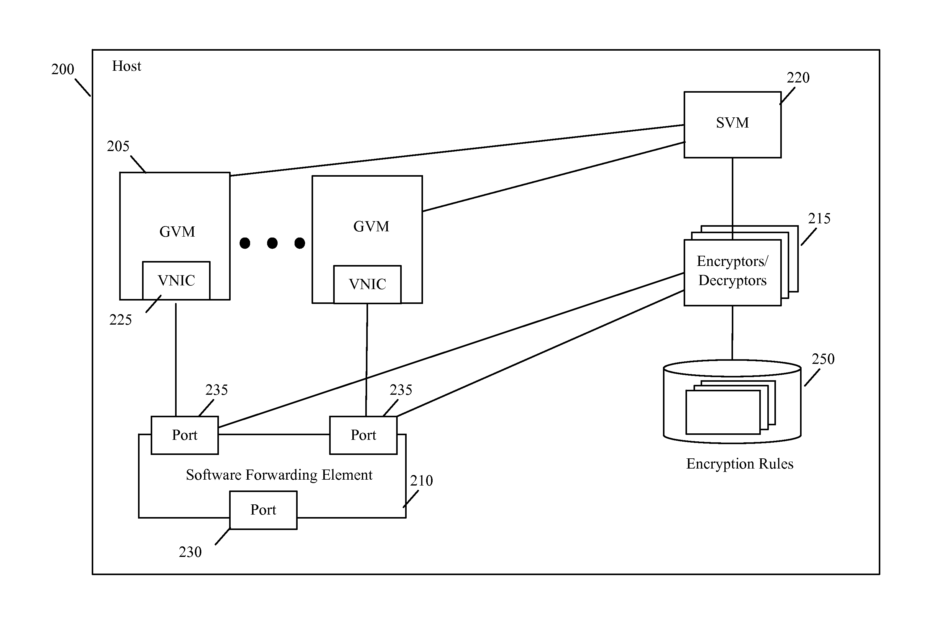
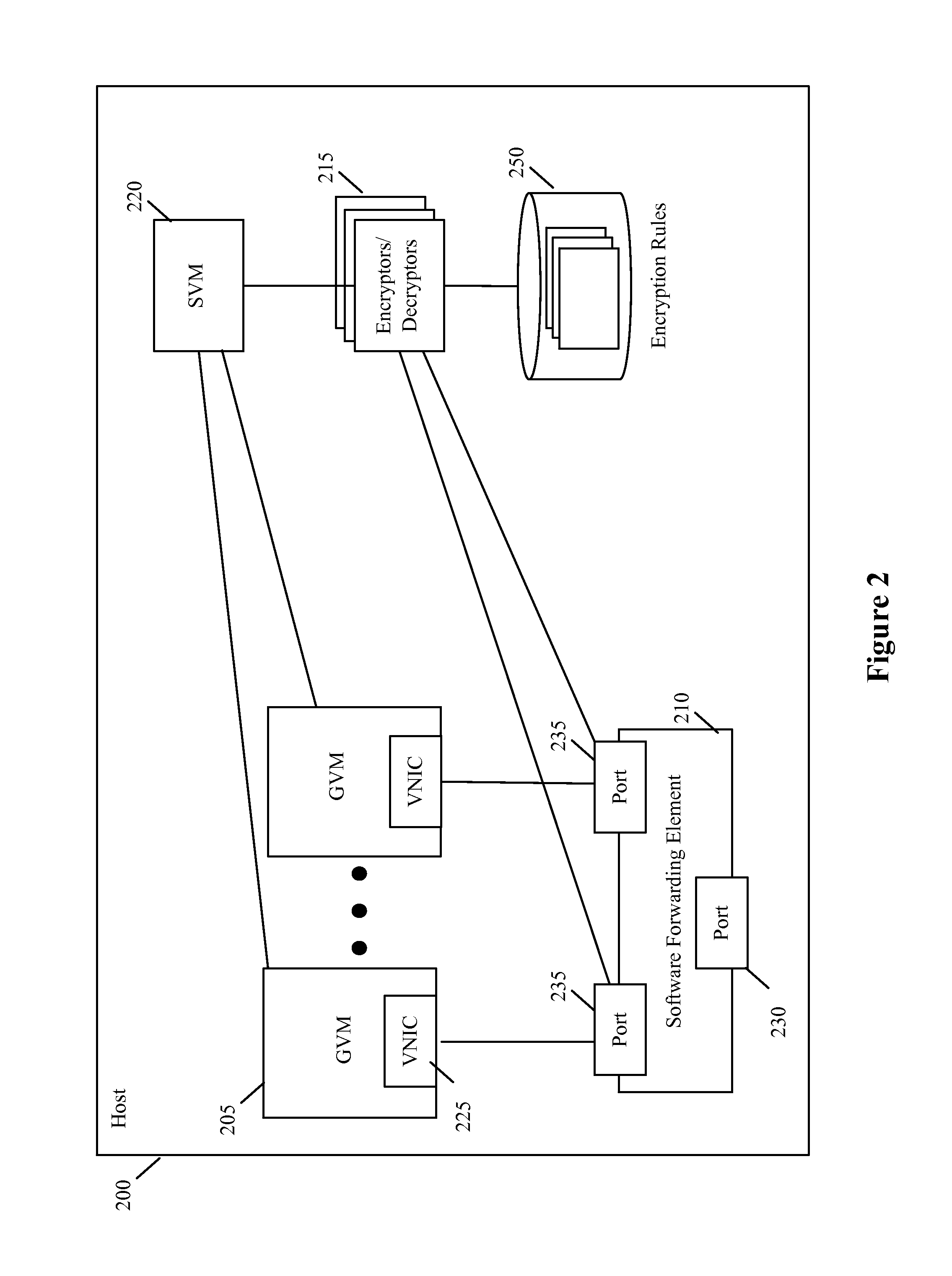
[0035]In the following detailed description of the invention, numerous details, examples, and embodiments of the invention are set forth and described. However, it will be clear and apparent to one skilled in the art that the invention is not limited to the embodiments set forth and that the invention may be practiced without some of the specific details and examples discussed.

[0036]For a host computing device (the “host”) that executes one or more guest virtual machines (GVMs), some embodiments provide a novel encryption method for encrypting the data messages sent by the GVMs. Examples of GVMs include webservers, application servers, database servers, etc. In some cases, all the GVMs belong to one entity, e.g., an enterprise that operates a datacenter with multiple hosts. In other cases, the host executes in a multi-tenant environment (e.g., in a multi-tenant data center), and different groups of GVMs belong to different tenants. As used in this document, encryption refers to the ...


PUM


Abstract

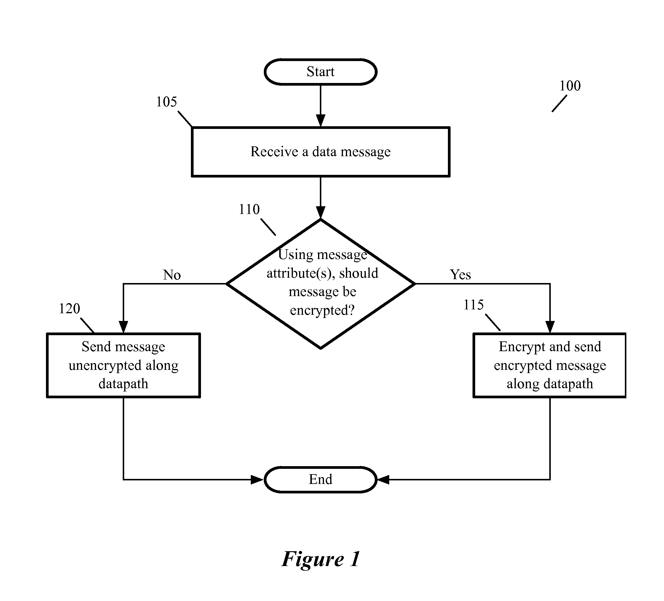
For a host that executes one or more guest virtual machines (GVMs), some embodiments provide a novel encryption method for encrypting the data messages sent by the GVMs. The method initially receives a data message to send for a GVM executing on the host. The method then determines whether it should encrypt the data message based on a set of one or more encryption rules. When the process determines that it should encrypt the received data message, it encrypts the data message and forwards the encrypted data message to its destination; otherwise, the method just forwards the received data message unencrypted to its destination. In some embodiments, the host encrypts differently the data messages for different GVMs that execute on the host. When two different GVMs are part of two different logical overlay networks that are implemented on common network fabric, the method in some embodiments encrypts the data messages exchanged between the GVMs of one logical network differently than the data messages exchanged between the GVMs of another logical network. In some embodiments, the method can also encrypt different types of data messages from the same GVM differently. Also, in some embodiments, the method can dynamically enforce encryption rules in response to dynamically detected events, such as malware infections.

Description

BACKGROUND[0001]Enterprises (e.g., financial service providers, healthcare providers, critical infrastructure providers, etc.) store valuable data, and transfer it over networks. Information spreads across datacenters often through dedicated telco-provided networks. Overlay networks provide the same service across the wide area network (WAN) on a public network for enterprises, and are susceptible to threats such as snooping, man in the middle attack (MITM), and forging. As enterprises widely adopt cloud-based Software-Defined Data Center (SDDC) instead of dedicated datacenters, new challenges are introduced, and protecting the data flowing into, within, and out of the cloud becomes a necessity. The privacy guarantee of private datacenters is no longer assumed, and threats similar to those in the Internet prevail.[0002]Cryptography protects data and communication channels from malicious parties, provides confidentiality to enterprise dataflow in the cloud, and provides control over ...

Claims


Application Information

Patent Timeline
IPC IPC(8): H04L9/14G06F9/455
CPCG09C1/00H04L63/123G06F9/45558G06F2009/45587H04L63/1408H04L63/1441G06F21/6236G06F21/568G06F2221/034G06F9/542G06F21/56H04L9/14H04L2209/24H04L63/0428G06F21/602
Inventor THOTA, KIRAN KUMARFEROZ, AZEEMWIESE, JAMES CHRISTOPHER
Owner NICIRA
Learn More