In-vehicle step-down switching power supply, in-vehicle electronic control device, and idle stop system

a technology of electronic control device and power supply, which is applied in the direction of electric variable regulation, process and machine control, instruments, etc., can solve the problems that the switching power supply may not normally operate, and achieve the effect of reducing electromagnetic noise and stable step-down switching operation

Active Publication Date: 2016-01-07
HITACHI ASTEMO LTD
View PDF4 Cites 5 Cited by
  • Summary
  • Abstract
  • Description
  • Claims
  • Application Information

AI Technical Summary

Benefits of technology

[0009]According to the present invention, even when an input voltage decreases, a stable step-down switching operation is enabled and electromagnetic noise can be suppressed.

Problems solved by technology

However, because an on / off-period of a main switch element cannot be made to become zero, from a restriction of securing a gate driving voltage of the main switch by a bootstrap circuit or a minimum on / off transition duration of a switching element, there is a duty allowance range such as 5 to 95% in D. If D is more than a value in the allowance range, a switching power supply may not normally operate.

Method used


Image

  • In-vehicle step-down switching power supply, in-vehicle electronic control device, and idle stop system
  • In-vehicle step-down switching power supply, in-vehicle electronic control device, and idle stop system
  • In-vehicle step-down switching power supply, in-vehicle electronic control device, and idle stop system

Examples


first embodiment

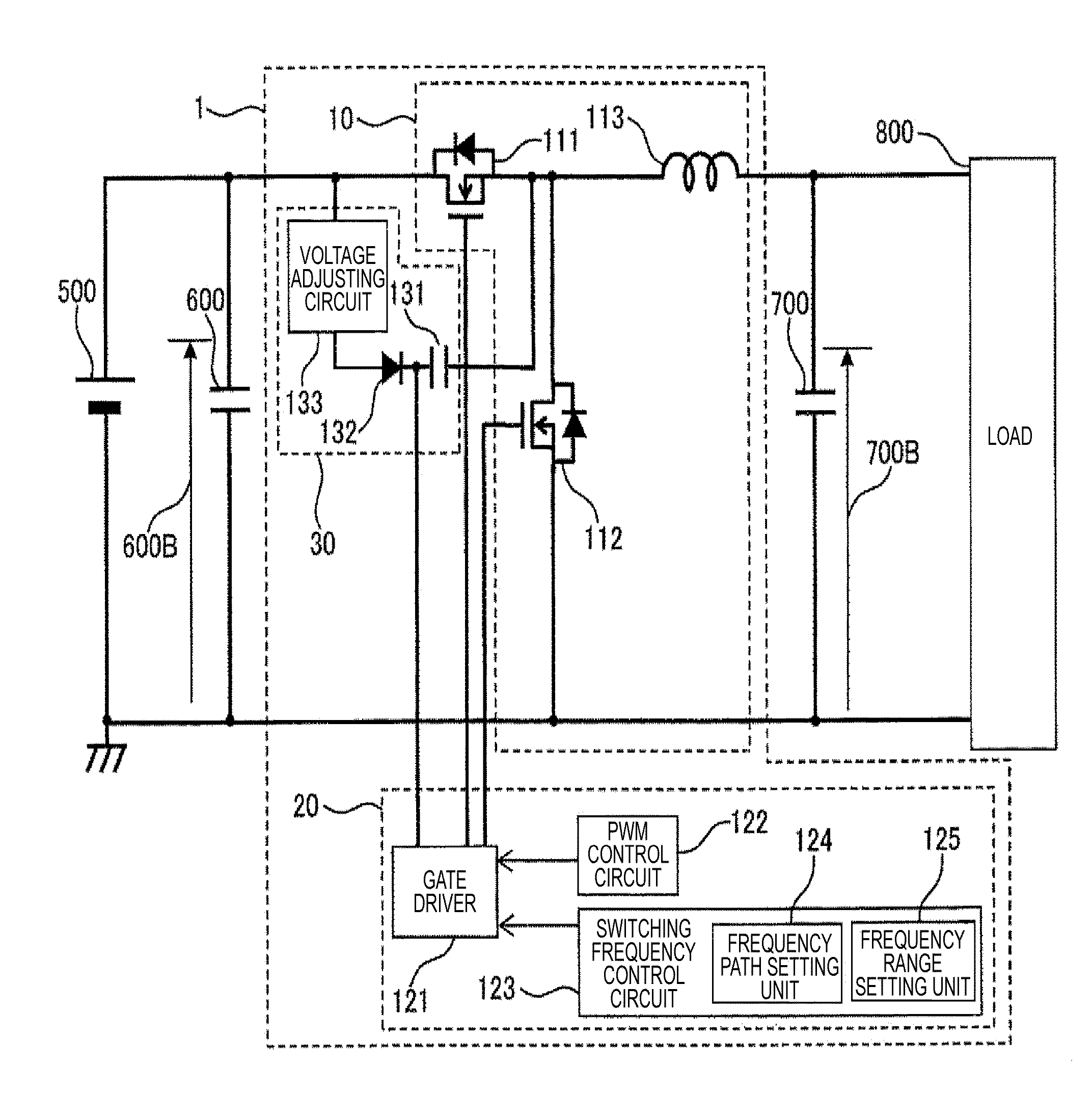
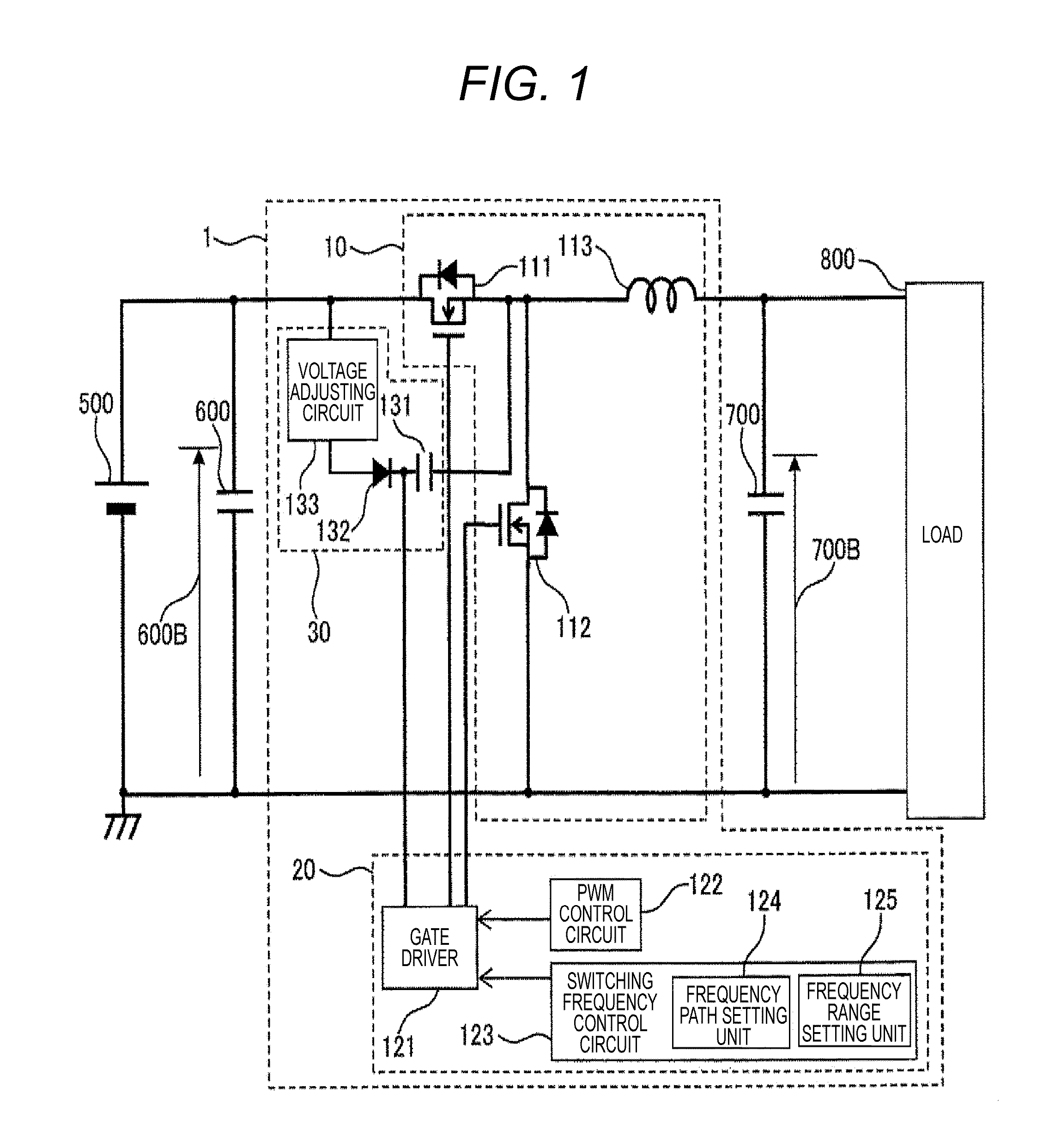
[0019]Hereinafter, a first embodiment of an in-vehicle step-down switching power supply according to the present invention will be described in detail using FIGS. 1 and 2. FIG. 1 illustrates a structural view of a power supply circuit of an in-vehicle control device including the in-vehicle step-down switching power supply according to the first embodiment.

[0020]The in-vehicle control device is connected to a battery 500 to be an in-vehicle power supply and includes an input-side capacitor 600, a step-down switching power supply circuit 1, an output-side capacitor 700, and a load 800. The step-down switching power supply circuit 1 includes a main circuit unit 10, a control circuit unit 20, and a bootstrap circuit unit 30.

[0021]The main circuit unit 10 includes an n channel type MOSFET 111 to be a main switch, an N channel type MOSFET 112 for synchronous rectification, and a main coil 113 for output voltage smoothing. The MOSFET 111 and the MOSFET 112 are switched by a gate driving s...

second embodiment

[0056]Hereinafter, a first embodiment of the in-vehicle step-down switching power supply according to the present invention will be described in detail using FIGS. 1 and 3. FIG. 3 is a diagram corresponding to FIG. 2 in the first embodiment. The same portions as the first embodiment are denoted with the same reference numerals and explanation thereof is omitted. Hereinafter, different portions will be described.

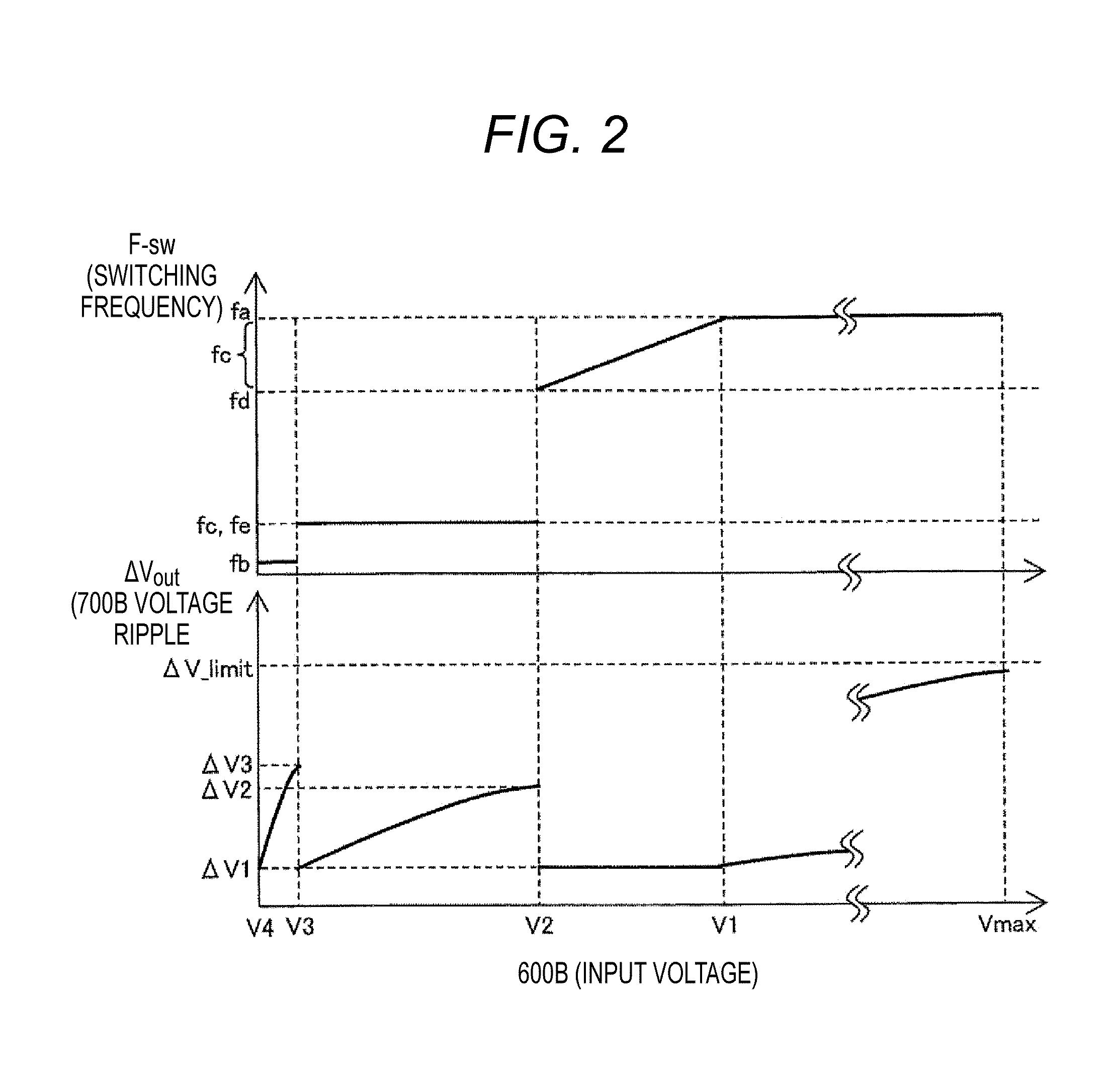
[0057]FIG. 3 is different from FIG. 2 in setting of fc in a range of V2 to V1. In the range of V2 to V1, fc is set as fc=fd to a constant value, so that ΔVout when an input voltage 600B changes from V1 to less than V1 becomes ΔV4. At this time, ΔVout and Toff can satisfy Toff>250 [ns] and ΔVout<20 [mV] as follows.

[0058]In the case of 600B=V1=6.8 [V] and F−sw=460 [kHz], ΔVout=ΔV1=3.1 [mV] and Toff=256 [ns] are satisfied.

[0059]In the case of 600B=V1=6.8 [V] and F−sw=300 [kHz], ΔVout=ΔV4=4.7 [mV] and Toff=390 [ns] are satisfied.

[0060]In addition, even when the frequency decrease...

third embodiment

[0062]Hereinafter, a third embodiment of the in-vehicle power supply device according to the present invention will be described in detail using FIG. 4. In general, an electrolytic capacitor includes an explosion-proof valve to prevent the explosion at the time of the temperature rise. In the case of amounting form of resin sealing, the explosion-proof valve is blocked and it is difficult to secure safety. For this reason, the electrolytic capacitor cannot be used.

[0063]According to the first and second embodiments, because the capacities of the input-side capacitor and the output-side capacitor can be decreased, the electrolytic capacitor used in the related art can be replaced with a ceramic capacitor. For this reason, mounting of the form of the resin sealing is enabled. If the resin sealing is enabled, semiconductor components can be subjected to bare chip mounting and miniaturization is enabled.

[0064]FIG. 4 illustrates the case in which the step-down switching power supply acco...


PUM


Abstract

Provided is an in-vehicle step-down switching power supply capable of obtaining a stable output while suppressing nose in a harmful frequency band even when an input voltage decreases. The in-vehicle step-down switching power supply includes a switching frequency control unit and the switching frequency control unit includes a switching frequency range setting unit that changes a switching frequency between fa and fb and a switching frequency path setting unit that skips a frequency band from fd to fe between fa and fb, via an intermediate frequency fc between fa and fb.

Description

TECHNICAL FIELD[0001]The present invention relates to an in-vehicle step-down switching power supply, an in-vehicle electronic control device having the in-vehicle step-down switching power supply mounted thereto, and an idling stop system having the in-vehicle step-down switching power supply mounted thereto.BACKGROUND ART[0002]In a general in-vehicle step-down switching power supply, a step-down ratio is adjusted by controlling a duty (D: ratio (D=Ton / T) of a switching cycle (T) and an on-period (Ton)) of a PWM signal input to a gate of a main switch. Because D is determined by a ratio Vout / Vin of an input voltage (Vin) and an output voltage (Vout), D approaches 100% when Vin decreases and approaches Vout. However, because an on / off-period of a main switch element cannot be made to become zero, from a restriction of securing a gate driving voltage of the main switch by a bootstrap circuit or a minimum on / off transition duration of a switching element, there is a duty allowance ran...

Claims


Application Information

Patent Timeline
Patent Type & Authority Applications(United States)
IPC IPC(8): B60L11/18H02M3/158
CPCH02M3/158B60L11/18H02M1/08H02M1/14H02M1/44H02M3/156H02M1/0006Y02T10/70B60L50/50
Inventor HATANAKA, AYUMUMAYUZUMI, TAKUYASATO, CHIHIRO
Owner HITACHI ASTEMO LTD
Why Eureka
Try Eureka