Wireless power transmission system

a power transmission system and wireless technology, applied in the direction of transformers, inductances, transportation and packaging, etc., can solve the problem of small resistance component relative to reactance component, and achieve the effect of reducing the potential variation of reference potential in the power reception apparatus

Active Publication Date: 2016-01-07
MURATA MFG CO LTD
View PDF3 Cites 5 Cited by
  • Summary
  • Abstract
  • Description
  • Claims
  • Application Information

AI Technical Summary

Benefits of technology

[0006]Accordingly, the present invention is directed to providing a wireless power transmission system capable of stabilizing an operation of a load circuit in a power reception apparatus.
[0008]With this configuration, as the four reactance elements are provided so as to match the ratio of the capacitance Cpp produced between the second electrode and the fourth electrode to the capacitance Caa produced between the first electrode and the third electrode, a potential difference between a reference potential point in the power transmission apparatus and a reference potential point in the power reception apparatus can be brought to 0. Thus, a potential variation of the reference potential in the power reception apparatus can be reduced, and an operation of the load circuit in the power reception apparatus can be stabilized.
[0011]Here, the shield electrode is provided in order to suppress radiation of noise generated from the feeder circuit in the power transmission apparatus. In this configuration, a node between the first reactance element and the second reactance element is connected to the reference potential with the shield electrode interposed therebetween. Then, as the shield electrode, which has an area sufficient to block the noise, is added to a conductor constituting the reference potential on the power transmission side, the reference potential in the power transmission apparatus can be stabilized. Through this configuration, a problem that unwanted noise is conducted (leaks) to a power supply line as the reference potential of the power transmission apparatus varies relative to the earth potential can be prevented. In addition, the potential difference between the reference potential point in the power transmission apparatus and the reference potential point in the power reception apparatus can be brought to 0. Thus, the potential variation of the reference potential in the power reception apparatus is reduced, and the operation of the load circuit in the power reception apparatus can be stabilized.
[0013]Here, the shield electrode is provided in order to suppress radiation of noise generated from a high-voltage portion (load circuit) in the power reception apparatus. In this configuration, a node between the third reactance element and the fourth reactance element is connected to the reference potential with the shield electrode interposed therebetween. Then, as the shield electrode, which has an area sufficient to block the noise, is added to a conductor constituting the reference potential on the power reception side, the reference potential in the power reception apparatus can be stabilized, and thus the operation of the load circuit in the power reception apparatus can be stabilized. In addition, the potential difference between the reference potential point in the power transmission apparatus and the reference potential point in the power reception apparatus can be brought to 0, and the potential variation of the reference potential in the power transmission apparatus is reduced. Thus, a problem that unwanted noise is conducted (leaks) to the power supply line due to a variation of the reference potential of the power transmission apparatus relative to the earth potential can be prevented.
[0016]According to the present invention, a potential variation of the reference potential in the power reception apparatus can be reduced, and the operation of the load circuit in the power reception apparatus can be stabilized.

Problems solved by technology

However, the resistance component is sufficiently small with respect to a reactance component.

Method used


Image

  • Wireless power transmission system
  • Wireless power transmission system
  • Wireless power transmission system

Examples


first embodiment

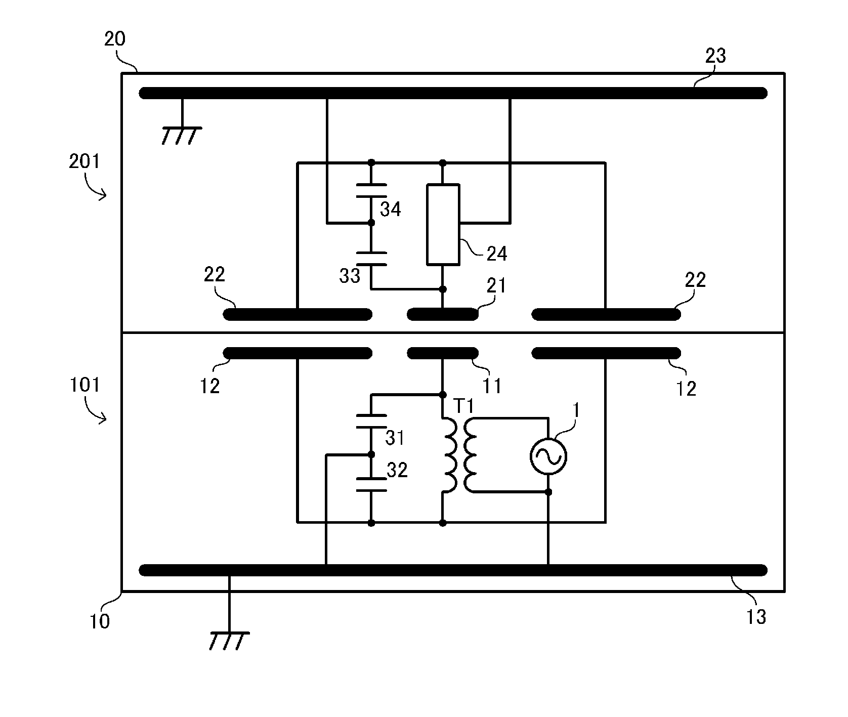
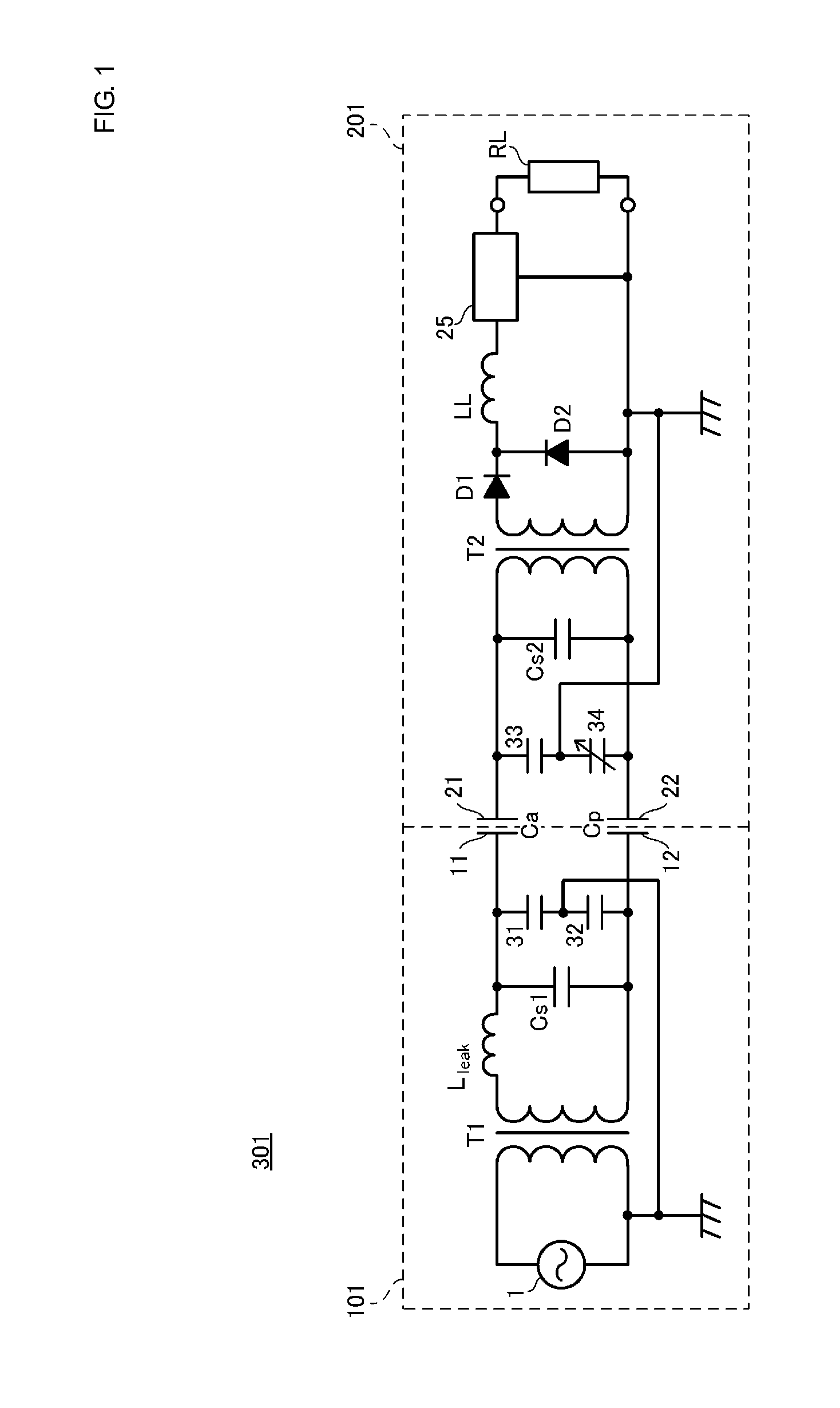
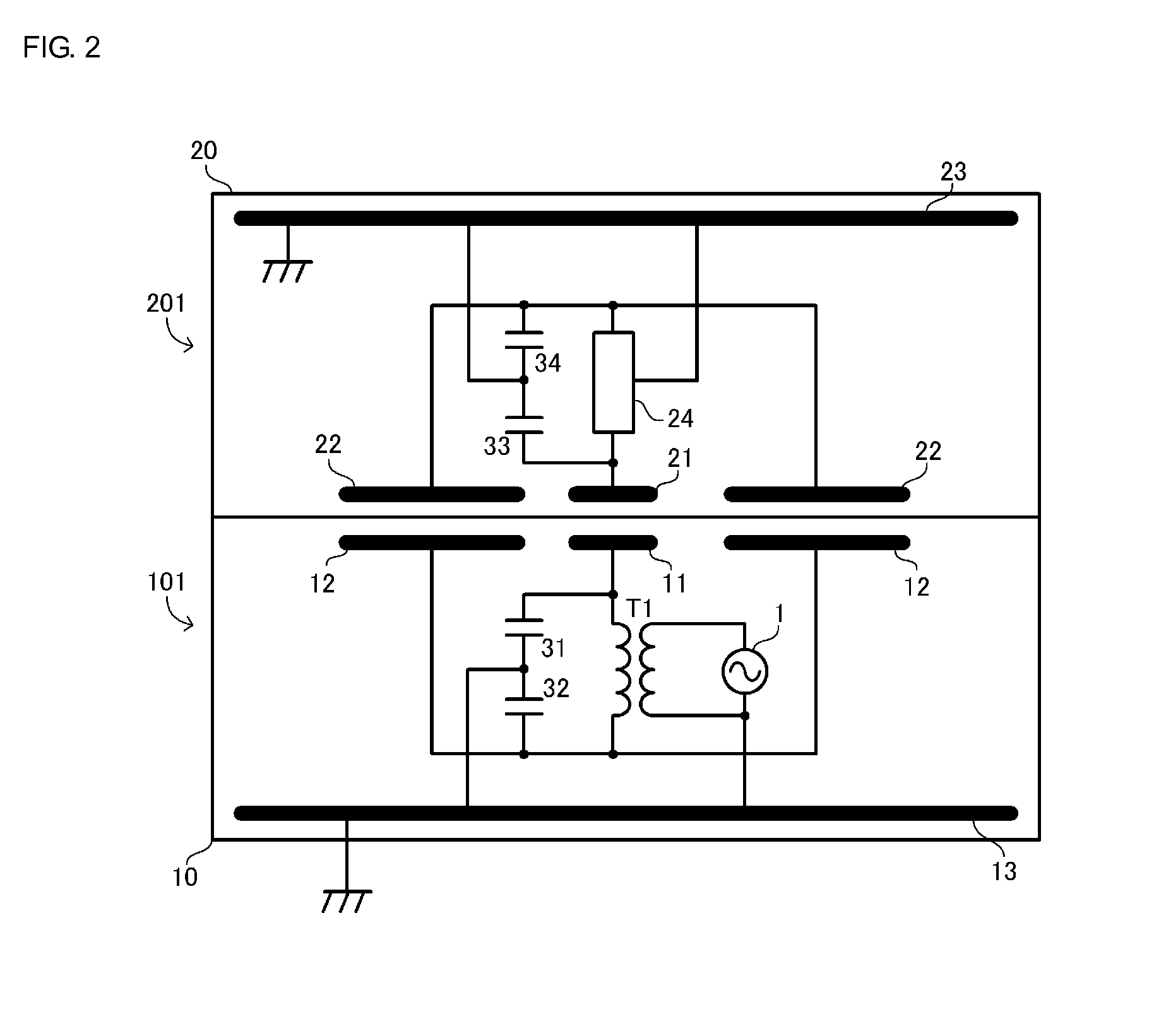
[0029]FIG. 1 is a circuit diagram of a wireless power transmission system 301 according to a first embodiment. The wireless power transmission system 301 includes a power transmission apparatus 101 and a power reception apparatus201. The power reception apparatus 201 includes a load circuit RL. The load circuit RL includes a secondary battery, a charging circuit for the secondary battery, a touch panel, which serves as an input unit, and so on, and none of them are illustrated. The power reception apparatus 201 is, for example, a portable electronic apparatus. Examples of the portable electronic apparatus include a cellular phone, a PDA, a portable music player, a laptop computer, and a digital camera. The power reception apparatus 201 is placed on the power transmission apparatus 101, and the power transmission apparatus 101 charges the secondary battery of the power reception apparatus 201.

[0030]The touch panel operates on the secondary battery serving as a power source.

[0031]Refe...

second embodiment

[0076]A wireless power transmission system according to a second embodiment differs from the wireless power transmission system according to the first embodiment in terms of a power reception apparatus. Hereinafter, the differences will be described.

[0077]FIG. 9 is an equivalent circuit diagram of a wireless power transmission system 302 according to the second embodiment. The wireless power transmission system 302 includes a power transmission apparatus 102 and a power reception apparatus 202. The power transmission apparatus 102 is identical to the power transmission apparatus 101 according to the first embodiment, and thus description thereof will be omitted.

[0078]In the power reception apparatus 202, inductors 35 and 36 connected in series between the active electrode 21 and the passive electrode 22 are provided. Specifically, the inductor 35 is connected to the active electrode 21, and the inductor 36 is connected to the passive electrode 22. A node between the inductors 35 and...

third embodiment

[0082]In a wireless power transmission system according to the present embodiment, capacitances corresponding to the capacitors 31, 32, 33, and 34 described in the first embodiment are formed by parasitic capacitances produced in a power transmission apparatus and a power reception apparatus, and the reference potential of the power reception apparatus is stabilized. Hereinafter, the differences will be described.

[0083]FIG. 10 is a sectional view conceptually illustrating primary portions of a power transmission apparatus 103 and a power reception apparatus 203 that constitute a wireless power transmission system 303 according to a third embodiment. FIG. 11 is a circuit diagram of the wireless power transmission system 303 illustrated in FIG. 10. It is to be noted that the capacitors Cs1 and Cs2 are omitted in FIG. 11.

[0084]In the wireless power transmission system 303, the power transmission apparatus 103 and the power reception apparatus 203 include shield electrodes 13A and 23A, ...


PUM


Abstract

A power transmission apparatus includes capacitors connected in series between an active electrode and a passive electrode. A power reception apparatus includes capacitors connected in series between an active electrode and a passive electrode. When a capacitance between the active electrodes is represented by Caa, a capacitance between the passive electrodes is represented by Cpp, and reactances of the capacitors are represented by X1, X2, X3, and X4; the active electrodes, the passive electrodes and the capacitors are configured such that Cpp / Caa=X1 / X2=X3 / X4 and Cpp≧Caa are satisfied. Thus, a wireless power transmission system capable of stabilizing an operation of a load circuit in the power reception apparatus is provided.

Description

CROSS REFERENCE TO RELATED APPLICATIONS[0001]The present application is a continuation of PCT / JP2014 / 056837 filed Mar. 14, 2014, which claims priority to Japanese Patent Application No. 2013-056855, filed Mar. 19, 2013, and to Japanese Patent Application No. 2014-031873, filed Feb. 21, 2014, the entire contents of each of which are incorporated herein by reference.FIELD OF THE INVENTION[0002]The present invention relates to wireless power transmission systems that transmit power through capacitive coupling (electric-field coupling).BACKGROUND OF THE INVENTION[0003]Patent Document 1 discloses a wireless power transmission system that transmits power through capacitive coupling. The wireless power transmission system described in Patent Document 1 is constituted by a power transmission apparatus that includes a high-frequency high-voltage generator, a passive electrode, and an active electrode, and a power reception apparatus that includes a high-frequency high-voltage load, a passive...

Claims


Application Information

Patent Timeline
Patent Type & Authority Applications(United States)
IPC IPC(8): H02J5/00H02J7/02
CPCH02J7/025H02J5/005H04B5/0012H02J50/05
Inventor ICHIKAWA, KEIICHISUESADA, TSUYOSHISAKAI, HIRONORI
Owner MURATA MFG CO LTD
Why Eureka
Try Eureka