Segmentation of large objects from multiple three-dimensional views

a three-dimensional view and large object technology, applied in the field of three-dimensional ultrasound imaging, can solve the problems of difficult to realize clinical practice, difficult to manually segment an organ in a 3d image, and inconvenient methods, etc., to facilitate registration and co-segmentation of ultrasound images, accurate calibration of tracking devices

Active Publication Date: 2016-01-14
KONINKLJIJKE PHILIPS NV
View PDF12 Cites 24 Cited by
  • Summary
  • Abstract
  • Description
  • Claims
  • Application Information

AI Technical Summary

Benefits of technology

[0013]It is a basic idea of the invention to use a tracking device, in particular an electromagnetic tracking device, to facilitate registration and co-segmentation of the ultrasound images. Via the viewpoint positions associated with each ultrasound image, and tracked with the tracking device, it is possible to roughly initialize a registration search space. Further exact results found via the co-segmentation and registration may be used to accurately calibrate the tracking device.
[0034]By this, the initialization is conveniently speeded up. As only a translation transformation is to be searched for as the viewpoint positions acquired with a tracking device may be taken into account, the initialization may be acquired very fast. Further, when dealing with only partly acquired objects, the co-segmentation and registration may be initialized in a very robust way.

Problems solved by technology

However, it is often tedious to manually segment an organ in a 3D image.
While quantification and visualization tools are relatively available for 2D images, 3D volumes analysis is often done by hand through tedious procedures difficult to realize in clinical practice.
Hence, such methods are quite inconvenient.
Automatically conducted and precise segmentations are therefore needed, but difficult to obtain, especially in ultrasound images which are corrupted by a lot of noise and various artifacts.
Ultrasound images do not provide the same medical information compared to e.g. the computer tomography (CT) or magnetic resonance (MR) modality.
However, ultrasounds can have issue visualizing in between the ribs, as the ribs cast a shadow masking information.
Also, ultrasound images have a limited field of view compared to computer tomography or magnetic resonance tomography.

Method used


Image

  • Segmentation of large objects from multiple three-dimensional views
  • Segmentation of large objects from multiple three-dimensional views
  • Segmentation of large objects from multiple three-dimensional views

Examples


Embodiment Construction

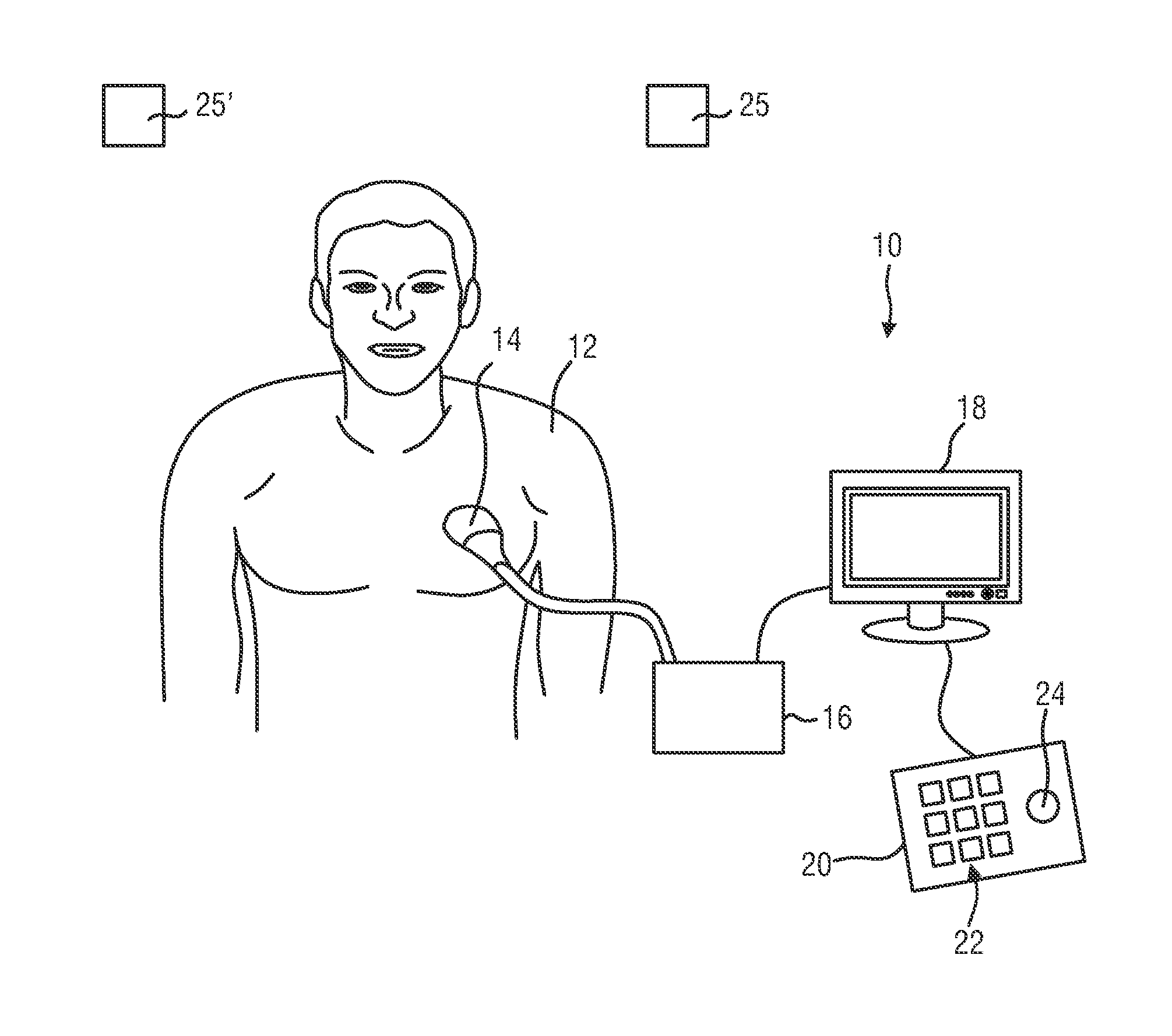
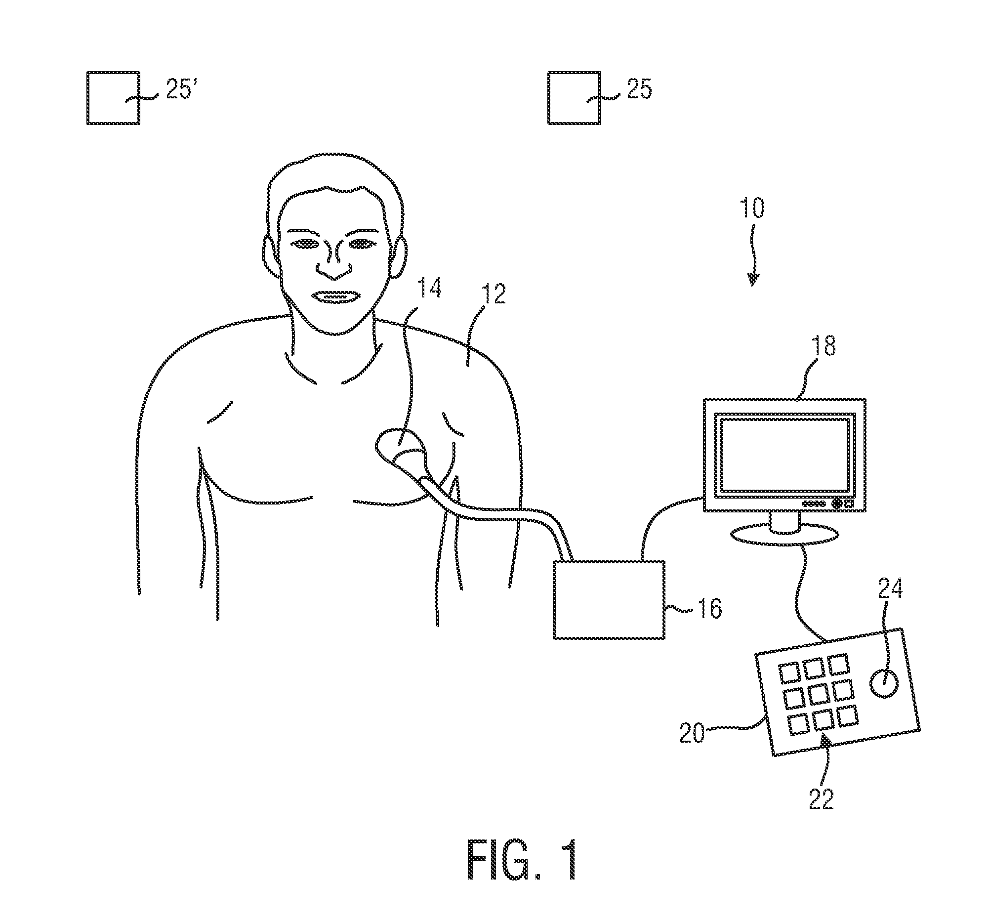
[0058]FIG. 1 shows a schematic illustration of an ultrasound system 10 according to an embodiment, in particular a medical ultrasound three-dimensional imaging system. The ultrasound imaging system 10 is applied to inspect a volume of an anatomical site, in particular an anatomical site of a patient 12. The ultrasound system 10 comprises an ultrasound image acquisition probe 14 having at least one transducer array having a multitude of transducer elements for transmitting and / or receiving ultrasound waves. In one example, the transducer elements each can transmit ultrasound waves in form of at least one transmit impulse of a specific pulse duration, in particular a plurality of subsequent transmit pulses. The transducer elements can for example be arranged in a one-dimensional row, for example for providing a two-dimensional image that can be moved or swiveled around an axis mechanically. Further, the transducer elements may be arranged in a two-dimensional array, in particular for ...


PUM


Abstract

The present invention relates to an ultrasound imaging system (10) for inspecting an object (33) in a volume (32). The ultra-sound imaging system comprises an ultrasound image acquisition probe (14) for acquiring three-dimensional ultrasound images and providing three-dimensional ultrasound image data, comprising a tracking device (25, 27) for tracking a position of the ultrasound image acquisition probe (14) and providing a viewpoint position (128, 130) of the three-dimensional ultrasound images. By this, an improved initialization and improved co-registration and co-segmentation is enabled by providing a plurality of three-dimensional ultrasound images and their respective viewpoint positions (128, 130), and to conduct a segmentation (80) of the object (33) simultaneously out of the plurality of three-dimensional ultrasound images and taking into account the viewpoint positions (128, 130).

Description

FIELD OF THE INVENTION[0001]The present invention relates to three-dimensional ultrasound imaging. In particular, the current invention relates to image processing and the segmentation of objects in a scanned volume.BACKGROUND OF THE INVENTION[0002]In three-dimensional ultrasound imaging, or volume imaging, the acquisition of a three-dimensional image can be performed differently according to the probe. For instance, using an xMatrix probe, for example the X6-1 of Philips, a genuine 3D acquisition can be performed. Using a mechanical probe, for example the V6-2 of Philips, the 3D volume is obtained from the acquisition of multiple two-dimensional slices whose calibration is driven mechanically. Using a two-dimensional probe, a three-dimensional volume is made by conducting many two-dimensional scans that slice through the volume of interest. Hence, a multitude of two-dimensional images is acquired that lie next to another. Further, by proper image processing, a three-dimensional ima...

Claims


Application Information

Patent Timeline
Patent Type & Authority Applications(United States)
IPC IPC(8): A61B8/08A61B8/00A61B8/13
CPCA61B8/523A61B8/085A61B8/13A61B8/4254A61B8/5261A61B8/461A61B8/467A61B8/58A61B8/5207A61B6/5247A61B8/4245A61B8/483A61B8/5223A61B8/5238G06T2207/10136G06T2207/30048A61B8/4263G06T7/30G06T7/149
Inventor DUFOUR, CECILEPREVOST, RAPHAEL MANUA MICHELMORY, BENOIT JEAN-DOMINIQUE BERTRAND MAURICEARDON, ROBERTO JOSE
Owner KONINKLJIJKE PHILIPS NV
Why Eureka
Try Eureka