
Plasma-Enhanced Atomic-Layer Deposition System and Method

a technology of atomic layer deposition and plasma, which is applied in the direction of chemical vapor deposition coating, coating, electric discharge tube, etc., can solve the problems of high activation energy, high heating temperature, and thin film technique that has not seen material breakthrough, etc., and achieves excellent uniformity, high film quality, and reduced reaction temperature

Inactive Publication Date: 2016-01-14
WANG DONGJUN
View PDF12 Cites 6 Cited by
  • Summary
  • Abstract
  • Description
  • Claims
  • Application Information

AI Technical Summary

Benefits of technology

This patent describes a method for depositing thin films using plasma-enhanced atomic layer deposition equipment. The method avoids precursor decomposition and desorption caused by excessive heating temperature and ensures an uncompromised chemical reaction process. The reaction temperature can be lowered, and many materials can be deposited only with the energy provided by the plasma without heating. The plasma is generated with remote inductively-coupled plasma generation, which prevents etching the thin film leading to high film quality. The method also allows for uniform distribution of plasma and precursors on the surface of the sample, resulting in excellent uniformity in the deposited thin film.

Problems solved by technology

Up until the late 1980s, this thin film technique had not seen material breakthrough, due to complicated surface chemistry involved and very low deposition rate.
Some precursors require high activation energy, which often requires very high heating temperature in such an ALD process.
In many cases, high heating temperature may cause precursor decomposition and / or desorption from the substrate, which prevents the reaction to occur, or leads to degraded film quality with high impurity content.
Some substrates, particularly those from organic compounds, cannot withstand high temperature, limiting the applicability of purely thermally activated ALD chemistries.

Method used


Image

  • Plasma-Enhanced Atomic-Layer Deposition System and Method
  • Plasma-Enhanced Atomic-Layer Deposition System and Method
  • Plasma-Enhanced Atomic-Layer Deposition System and Method

Examples


Embodiment Construction

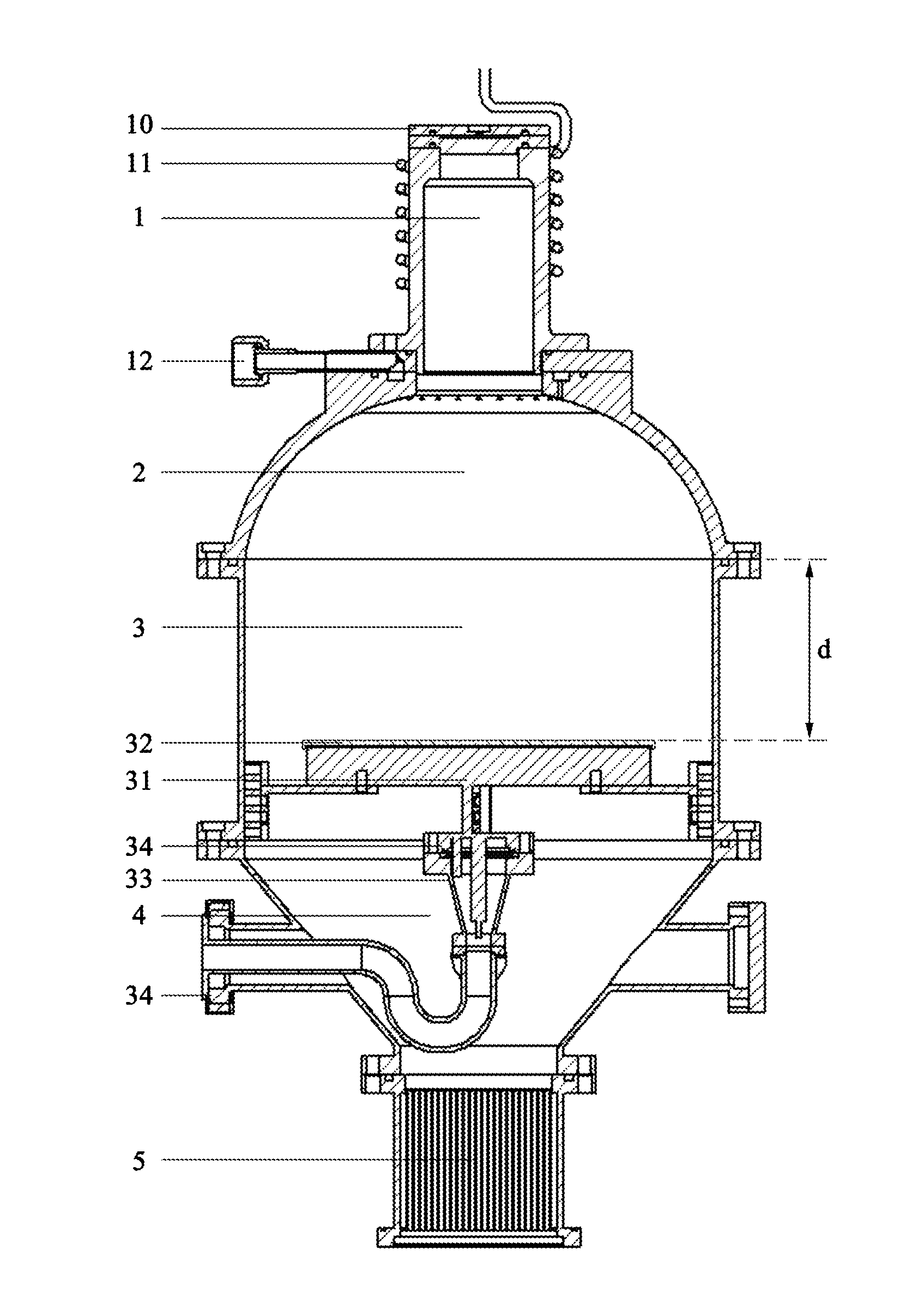
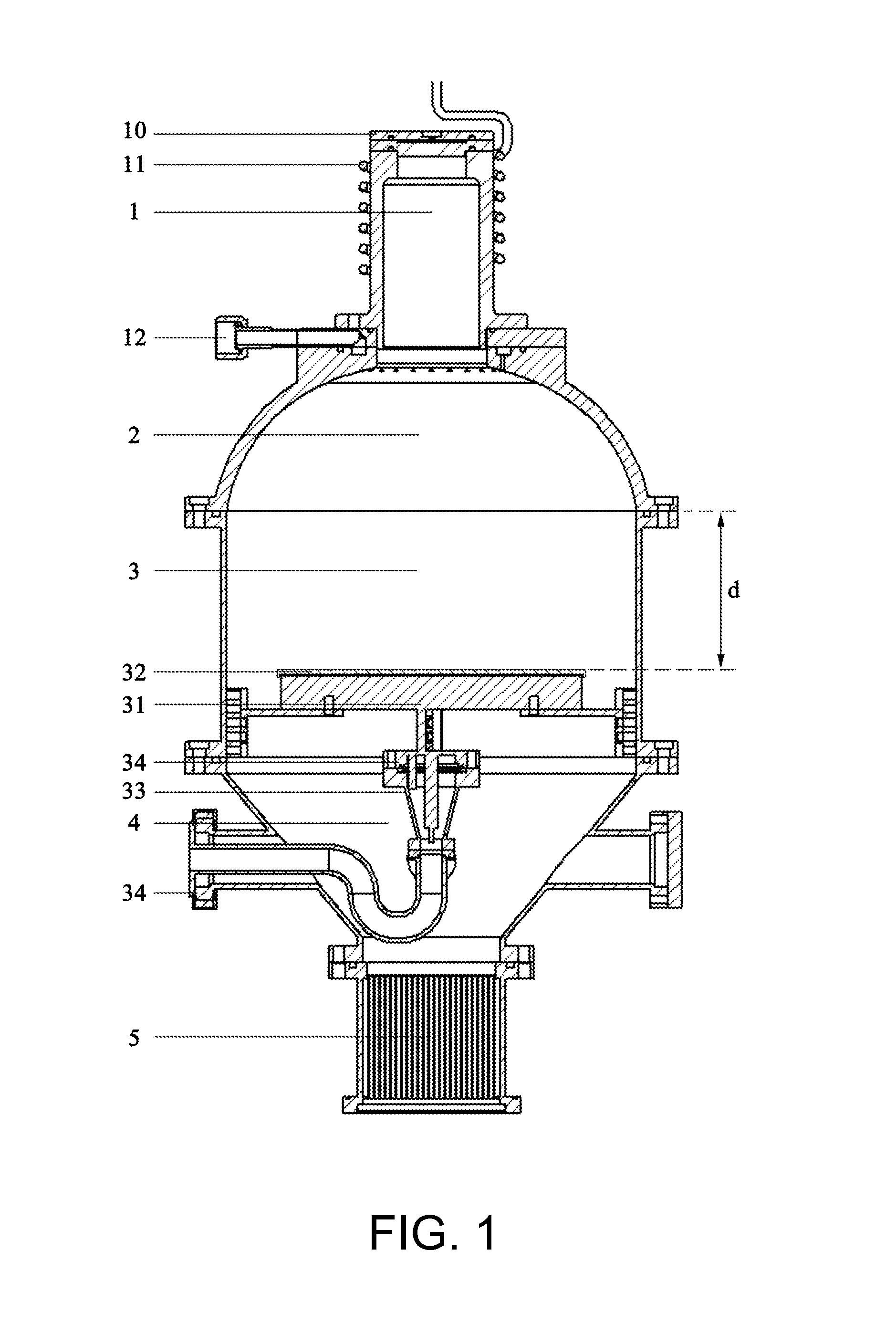
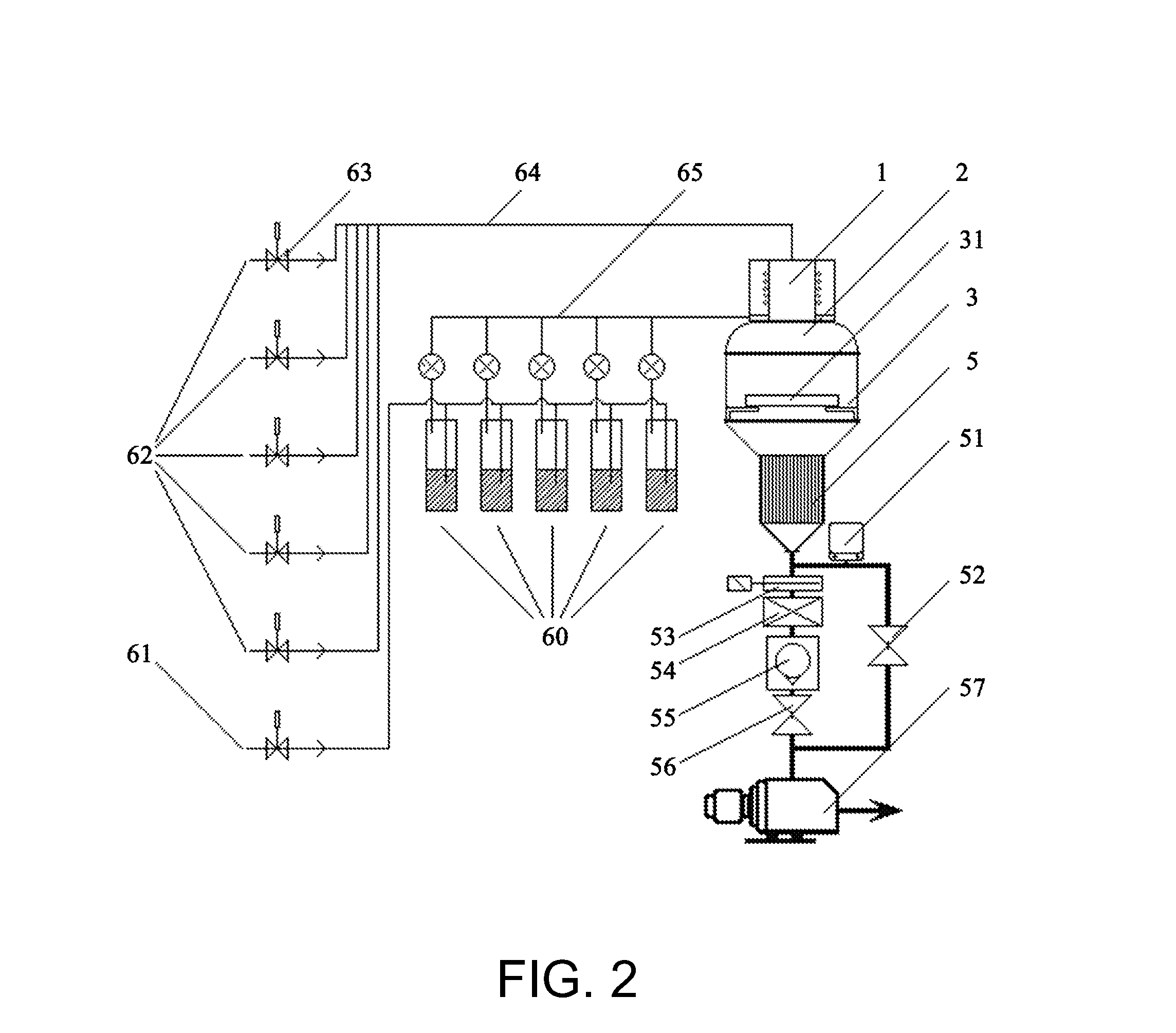
[0055]The content and detailed description of this invention are explained with illustration of the attached figures: As shown in FIG. 1, this invention discloses a type of plasma-enhanced atomic layer deposition equipment, including fluidly connected plasma generation chamber 1, diffusion chamber 2, reaction chamber 3, and pumping chamber 4, of which plasma generation chamber 1 consists of a plasma generation gas inlet(s) 10 and a plasma generation device(s), that generates plasma using the plasma generation gas coming from plasma generation gas inlet 10. A precursor inlet(s) 12 is located between the plasma generation chamber 1 and the diffusion chamber 2. Precursors coming from the precursor inlet 12 and generated plasma diffuse uniformly inside the diffusion chamber 2.

[0056]A sample stage 31 is located inside the reaction chamber 3 for the placement of sample(s), on the surface of which precursors and plasma react to form a thin film. Pumping chamber 4 is sequentially connected ...


PUM

PropertyMeasurementUnit
vertical distanceaaaaaaaaaa
thicknessaaaaaaaaaa
inner diameteraaaaaaaaaa

Abstract

In one example, we describe a type of plasma-enhanced atomic layer deposition equipment including: fluidly connected plasma generation chamber, diffusion chamber, reaction chamber, and pumping chamber, wherein the plasma generation chamber includes a plasma generation gas inlet and a plasma generation device that enables the generation of plasma from the plasma generation gas coming from the plasma generation gas inlet. A precursor inlet is disposed between the plasma generation chamber and the diffusion chamber. Precursors coming from the precursor inlet and generated plasma diffuse uniformly inside the diffusion chamber. A sample stage, for the placement of sample to be deposited on, is disposed inside the reaction chamber. The pumping chamber is sequentially connected to an exhaust trap and pumping system. The equipment has enabled high quality atomic layer thin film deposition.

Description

RELATED APPLICATION[0001]This current application is based on a PCT case, PCT / CN2013 / 073761, filed in China, on 3 Apr. 2013, whose teachings are incorporated herein by reference, and it also claims priority date of that PCT case.FIELD OF INVENTION[0002]This invention relates to one type of atomic layer deposition equipment, and more specifically, to one type of plasma-enhanced atomic layer deposition equipment.BACKGROUND OF THE INVENTION[0003]Atomic layer deposition (ALD), also known as atomic layer epitaxy, is a thin film deposition technique first proposed by Finnish scientists for preparation of polycrystalline photoluminescence ZnS:Mn films and amorphous Al2O3 films for the application in flat panel displays. Up until the late 1980s, this thin film technique had not seen material breakthrough, due to complicated surface chemistry involved and very low deposition rate.[0004]However, since the mid-1990s, interest in this technique has been steadily growing. Progress in microelectr...

Claims


Application Information

Patent Timeline
Patent Type & Authority Applications(United States)
IPC IPC(8): C23C16/44C23C16/455C23C16/458
CPCC23C16/4412C23C16/45544C23C16/45536C23C16/45559C23C16/4586C23C16/45565H01J37/321H01J37/32357H01J37/3244
Inventor WANG, DONGJUN
Owner WANG DONGJUN
Learn More