
Sustainable energy efficient roof system

a sustainable energy and roof technology, applied in the direction of roofing, roof covering using flexible materials, building repairs, etc., can solve the problems of parapet walls and sheet metal gutters, roofs are prone to expansion and contraction, wind failure,

Inactive Publication Date: 2016-01-14
KELLY THOMAS L
View PDF0 Cites 18 Cited by
  • Summary
  • Abstract
  • Description
  • Claims
  • Application Information

AI Technical Summary

Benefits of technology

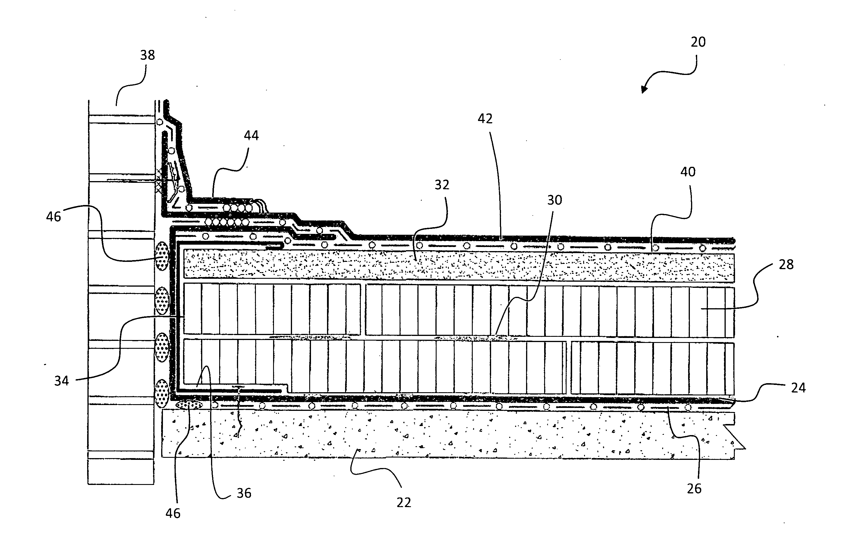
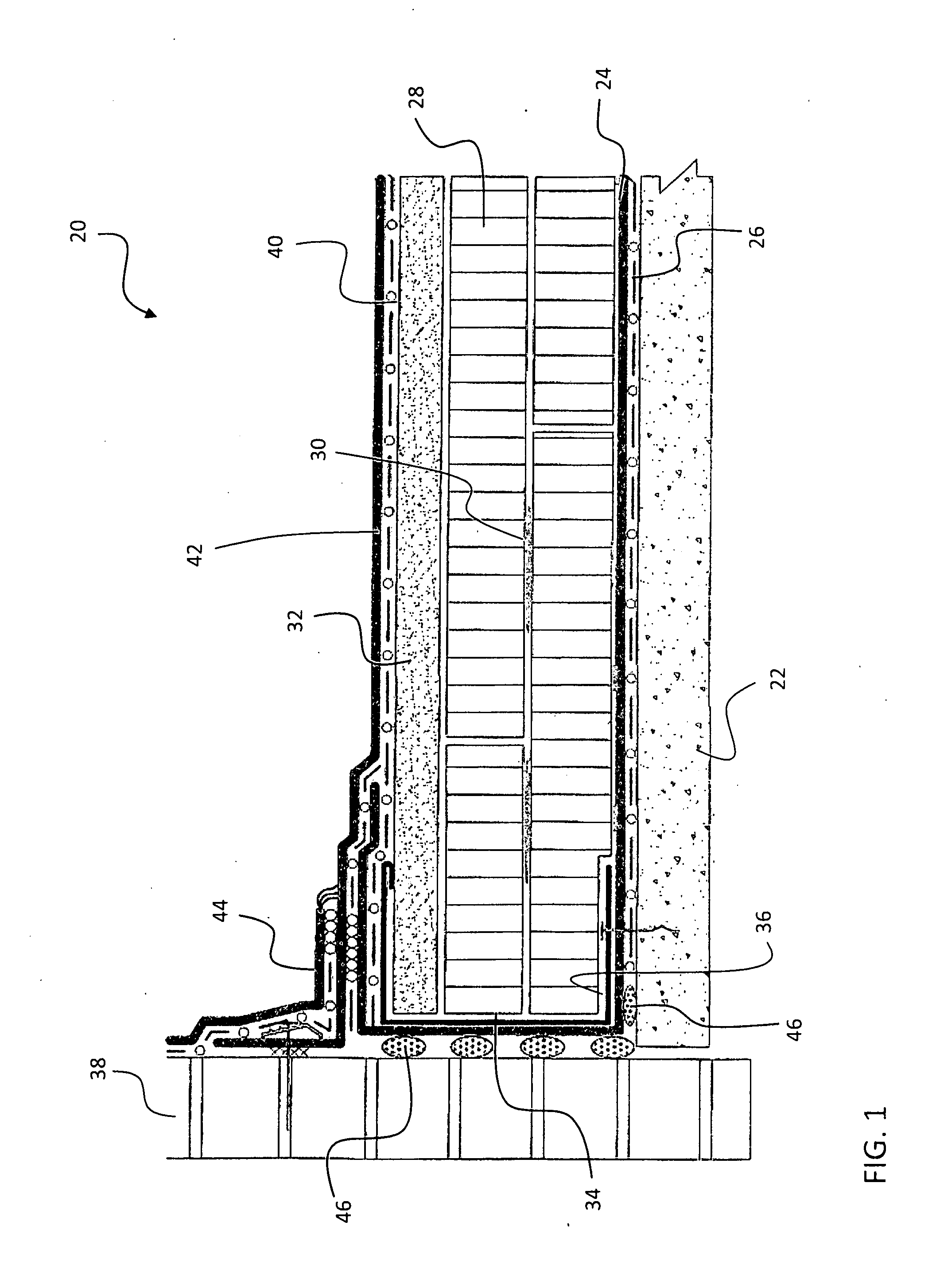
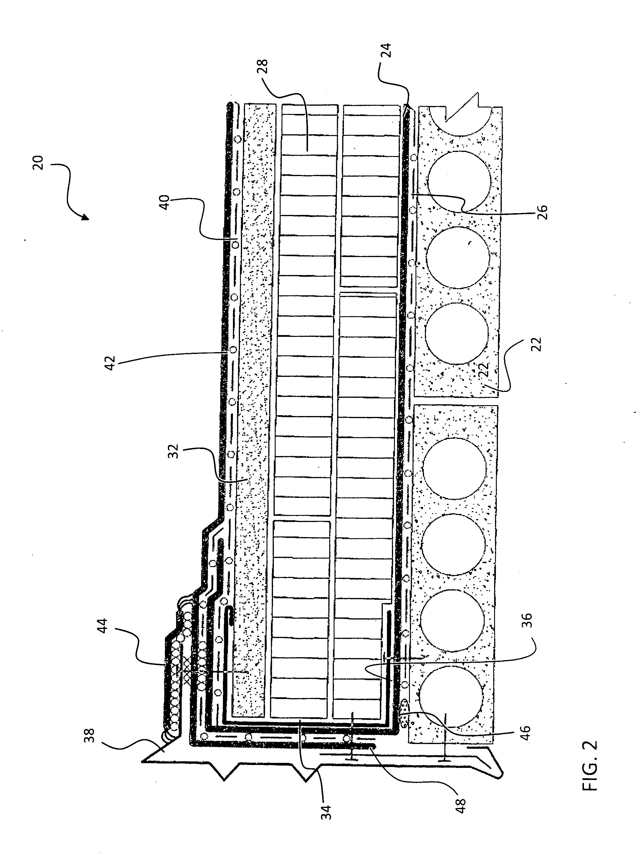
The invention provides a roof system and method that includes a roof deck, waterproofing membrane, and channel member for sealing the roof system. The channel member is secured to the roof deck and insulation is installed on top of the membrane with a weighted cover board on top. The first waterproofing membrane surrounds the channel member and extends over the weighted cover board, while a second waterproofing membrane is added over the weighted cover board and overlaps a portion of the first membrane. This results in a tight seal and improved protection of the roof system from water infiltration.

Problems solved by technology

Because the perimeter edge of the roof is an area that experiences forces that act in different directions as well as being an area where wind vortices create low pressure regions, the roof is prone to expansion and contraction as well as wind failure in this area.
Parapet walls and sheet metal gutters, gravel stops and fascia finishes can leak in this area damaging conventional perimeter membrane terminations.
Typical edge terminations, such as nailers, termination bars, reinforced membrane strips, and fasteners are prone to failure for mainly two reasons.
First, the pulling of the membrane due to high winds eventually tears the membrane at the stress concentration points created by discrete or non-uniform areas of membrane retention.
Second, moisture finds its way to the boards in which the retaining features are embedded, causing rotting that eventually results in the fasteners coming loose from the boards.

Method used


Image

  • Sustainable energy efficient roof system
  • Sustainable energy efficient roof system
  • Sustainable energy efficient roof system

Examples


Embodiment Construction

[0014]Referring now to FIG. 1, the illustrated embodiment of a roof system 20 includes a roof deck 22, such as formed from poured in place concrete for example. It will be understood by a person of ordinary skill in the art that other types of decks formed from either an air permeable or a non-air permeable material, including, but not limited to, tectum, gypsum, composite, wood, precast (FIG. 2), and corrugated metal (FIG. 4) for example, are within the scope of the invention. A first waterproofing membrane 24 is positioned upwardly adjacent the roof deck 22. In the illustrated, non-limiting embodiment, the first waterproofing membrane 24 is fully adhered to the roof deck 22, such as with a layer of vapor barrier adhesive 26 for example. The membrane 24 may be made of ethylene propylene diene monomer (EPDM), chlorosulfonated polyethylene (CSPE), polyvinyl chloride (PVC) or other similar roof waterproofing single ply membranes. In addition, each membrane described herein may include...


PUM


Abstract

A roof system is provided including a roof deck and a first waterproofing membrane disposed upwardly adjacent the roof deck. A channel member is arranged over a portion of the first waterproofing membrane near a perimeter of the roof system. The channel member is secured to the roof deck with a plurality of fasteners. Insulation is arranged upwardly adjacent the first waterproofing membrane A weighted cover board is disposed on top of the insulation. A portion of the insulation and the weighted cover board is arranged within the cavity of the channel member. The first waterproofing membrane surrounds the channel member and extends over a portion of an upper surface of the weighted cover board. A second waterproofing membrane is positioned upwardly adjacent the weighted cover board. The second waterproofing membrane overlaps the portion of the first waterproofing membrane extended over the weighted cover board.

Description

CROSS-REFERENCE TO RELATED APPLICATION[0001]This application claims the benefit of U.S. provisional patent application Ser. No. 62 / 022,535 filed Jul. 9, 2014, the entire contents of which are incorporated herein by reference.BACKGROUND[0002]Exemplary embodiments of the invention relate to a roof system, and more particularly, to a sealed roof system.[0003]Roofing systems use waterproof membrane to prevent water from entering into the building. Large sheets of such membranes are welded or glued to one another, depending on the material of the membrane, to form continuous sheets that cover the entire surface of the roof. Membranes generally require termination of one kind or another at a perimeter edge of the roof. Because the perimeter edge of the roof is an area that experiences forces that act in different directions as well as being an area where wind vortices create low pressure regions, the roof is prone to expansion and contraction as well as wind failure in this area. Parapet ...

Claims


Application Information

Patent Timeline
Patent Type & Authority Applications(United States)
IPC IPC(8): E04D11/02E04D3/02E04D3/35E04D3/36E04D5/00E04D5/14E04D13/00
CPCE04D11/02E04D3/02E04D3/352E04D13/00E04D5/00E04D5/148E04D3/3605E04D13/1415E04D13/155E04D13/1606E04D13/165
Inventor KELLY, THOMAS, L.
Owner KELLY THOMAS L
Learn More