Sustainable energy production

a technology of energy production and sustainable energy, applied in the direction of greenhouse gas reduction, thermal-pv hybrid energy generation, lighting and heating apparatus, etc., can solve the problems of little to no human intervention opportunity, difficult to challenge the increase of atmospheric carbon dioxide and the increase of carbon dioxide into the ocean, etc., to reduce instantaneous energy deficiencies in the system

Inactive Publication Date: 2019-12-19
REGRUT THOMAS
View PDF7 Cites 1 Cited by
  • Summary
  • Abstract
  • Description
  • Claims
  • Application Information

AI Technical Summary

Benefits of technology

[0019]In some embodiments, the system for storing excess energy comprises a compressor, powered by excess energy from the system for capturing solar energy solar to compress a fluid, at least one storage means for containing the compressed fluid, a an expander for expanding compressed fluid from the at least one storage means. The power generated by the expander is used to reduce instantaneous energy deficiencies in the system. In other embodiments, the system for storing excess energy comprises a gas liquefaction unit instead of a compressor. In many of these embodiments, the fluid compressed is air, and the gases, when liquified, may be separated into components.

Problems solved by technology

Also, there is still a great deal of discussion and debate concerning the question of whether it is due to human sources.
Regardless of the source, it is difficult to challenge the increases in atmospheric carbon dioxide and the increased levels of the carbon dioxide into the oceans.
These provide little to no opportunity for human intervention.
When greenhouse gases are mentioned, carbon dioxide receives a great deal of attention, yet other greenhouse gases pose a similar and perhaps greater threat.
Of these, the halocarbons, which are all substantially man-made, pose a very long-lasting threat.
That is very sobering, bad news; however, the full magnitude of the problem is far worse.
This is a very serious problem, which will only grow even more serious the longer that essentially nothing is done to address this problem, with the exception of endless debate on the topic of whether or not a problem exists.
The paralysis that has arisen due to this endless, charged debate has resulted in a lack of action to address this problem in a coordinated, effective manner.
Thus, the greenhouse gases in the atmosphere present the same obstacle to flow that the dam presented during the rainstorm.
Further delays will only make the final day of reckoning yet more disastrous.
Simply put, business cannot continue as usual, with an endless debate.
If we debate until the oceans boil, we will certainly have debated far too long.

Method used


Image

  • Sustainable energy production
  • Sustainable energy production

Examples


embodiment 10

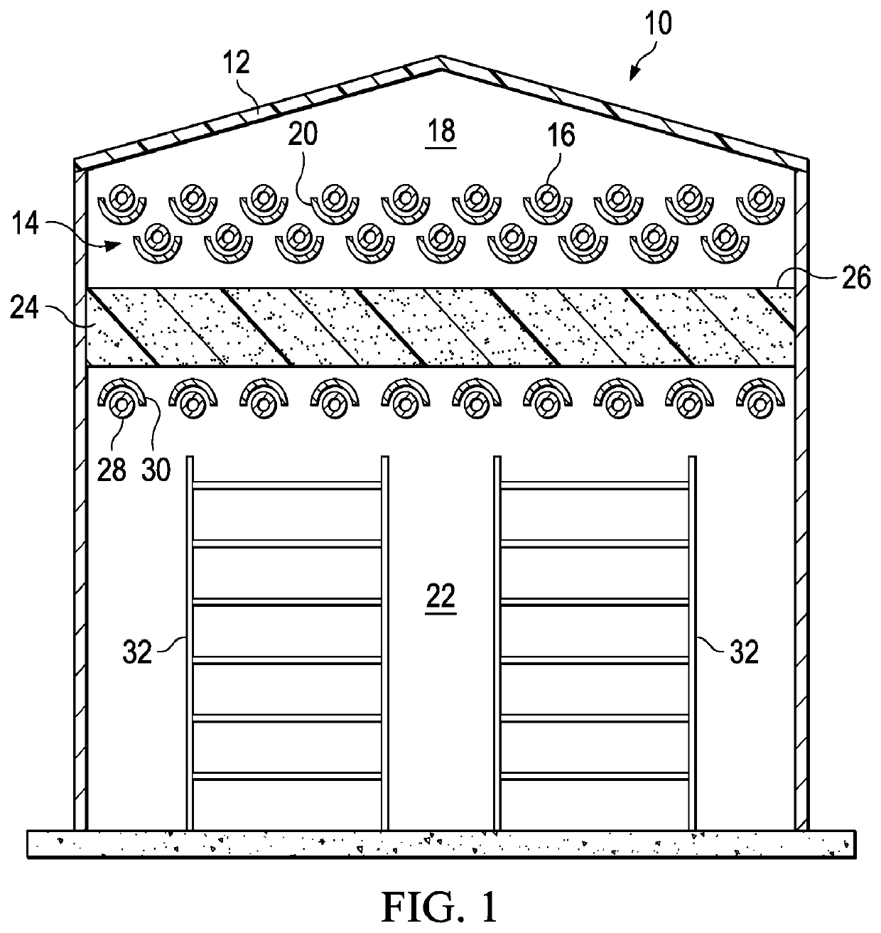
[0026]FIG. 1 illustrates schematically how a solar thermal application can be used to reduce electricity or natural gas usage. In the embodiment 10, a transparent or translucent roof 12 is used instead of a typical opaque roof. By doing this, the solar thermal apparatus 14, depicted as a series of tubes 16, is located inside the housing, in an attic space 18 in the depicted embodiment. This eliminates the need to be outside on a roof surface. In this embodiment, an appropriate heat transfer liquid (water being a good example) passes through the tubes 16 that are located in an attic space 18, acquiring heat in the process. An optional set of reflectors 20 is shown below each of the tubes 16. In a preferred embodiment, these reflectors 20 are mechanized to track the movement of the sun. The attic space 18 is separated from an inhabitable space 22 by an insulative layer 24. In addition to, or possibly instead of, the surface 26 that faces into the attic space 18 may be coated with a re...

embodiment 11

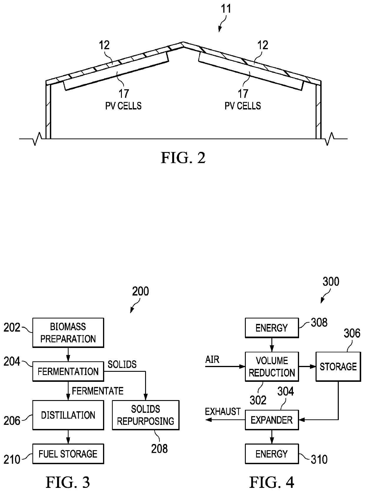
[0028]In another embodiment 11, as depicted in FIG. 2, a series of photovoltaic panels 17 are deployed, preferably immediately below and parallel to the roof surface 12. In this embodiment 11, the electricity produced in the photovoltaic panels 17 substitutes for electricity that would otherwise be drawn from the overall electrical grid.

[0029]These hybrid approaches to renewable energy are available in the middle latitudes of the United States and may be extendable to other geographical areas with similar seasonal climates through the deployment of the invention, a hybrid clean energy unit. From April through November, a solar thermal array can be configured at a residence or at an electricity generation facility. The array can be arranged similarly to those already in use, with the solar energy being used to preheat and / or boil water prior to being sent to a boiler, among other uses, reducing the need for fuel. In preferred embodiments, the solar collection would be by way of parab...


PUM

PropertyMeasurementUnit
energyaaaaaaaaaa
timeaaaaaaaaaa
energyaaaaaaaaaa

Abstract

To reduce the overall environmental impact of a residence or commercial facility, a system is provided for integrating energy usage. In such a system, there is a system for capturing solar energy; a system for fermenting biomass and concentrating the fermentate, generating carbon dioxide and ethanol; a system for storing excess energy for subsequent release; and a system for growing biomass. In integrating the systems, the captured solar energy is used as heat and electrical power. Excess energy beyond an instantaneous energy requirement is stored in the system for storing excess energy. Ethanol produced is used as a fuel. Carbon dioxide that is produced is provided to the system for growing biomass. Instantaneous energy deficiencies are reduced by releasing stored excess energy.

Description

TECHNICAL FIELD[0001]The embodiments disclosed herein relate to modifications and adaptations that are made to a pre-existent household, as well as to new constructions, for the purpose of reducing the energy footprint of the residents and the residence as well as an existing or future electricity generation facility. In addition, a scalable energy storage and electrical generation system is disclosed herein for a wide range of possible applications, from a household size all the way up to utility size for both renewable energy sources as well as traditional energy sources. Finally, a new construction method is disclosed herein which provides an optimal, attractive roof for the installation of photovoltaic cells and solar thermal equipment in the attic of homes or other types of buildings, providing a previously unused space the opportunity to contribute to the energy efficiency of the household or other type of building.BACKGROUND OF THE ART[0002]Much discussion has occurred lately...

Claims


Application Information

Patent Timeline
Patent Type & Authority Applications(United States)
IPC IPC(8): H02S40/44H02S20/22H02S40/22F24S20/40F24S20/60C12P7/08C12F3/02
CPCF24S20/40H02S20/22H02S40/22C12P7/08F24S20/60H02S40/44C12F3/02H02S10/00H02S20/23Y02P20/59Y02E10/52Y02E10/60Y02P20/133Y02E10/40C12M21/12H02S10/20C12M43/08Y02E70/30Y02B10/20
Inventor REGRUT, THOMAS
Owner REGRUT THOMAS
Why Eureka
Try Eureka