Stackable optical fiber adapter

a technology stackable parts, which is applied in the field of stackable optical fiber adapters, can solve the problems of difficult to improve the installation density, the entire spatial configuration cannot be properly arranged for actual application, and the amount of optical fiber adapters able to be installed on the panel with given standard size is limited, so as to achieve easy design, increase the density, and the effect of simple assembly structure of the shell member

Active Publication Date: 2016-01-14
CORNING OPTICAL COMM LLC
View PDF3 Cites 19 Cited by
  • Summary
  • Abstract
  • Description
  • Claims
  • Application Information

AI Technical Summary

Benefits of technology

[0011]According to main aspect of the present disclosure, a base of a shell member defines a plurality of mating parts formed at front and rear sides thereof, and an accommodating cavity is formed in the base and transversely communicated with the two opposite mating parts for insertion of an optical fiber connector. Each two adjacent bases of the plurality of shell members define at least one positioning part and corresponding wedged-jointing part at lateral sides thereof respectively, the positioning part and the wedged-jointing part respectively have a dovetail-shaped clasping block and a position-limiting groove which can be mounted with each other. Therefore, each two adjacent bases of the plurality of shell members can be vertically stacked, horizontally arranged in parallel or formed as an integral array structure by a modularized manner, and more shell members can be installed on the panel with higher density. The assembled structure of the shell member is simple and it is easy to design such mold, each shell member has constant number of the mating parts, so it is not necessary to develop different molds for the shell members having different amount of mating parts, the manufacturing process and amount of the molds can also be simplified, and the effects of stable structure, easy assembly, easy mass production and reduced cost can be achieved.

Problems solved by technology

However, in normal condition, the standard LC type optical fiber adapter is installed on rack-mount panel, and most manufacturers make effort in installing more optical fiber adapters in limited space of the panel for meeting the requirement of entire spatial configuration and efficiently solving the problem of limited bandwidth due to insufficient transmission channels.
The shell members A of the plurality of optical fiber adapters are respectively installed in the panel through the wing plates A2 to assemble a 4×4 array structure, but each two adjacent shell members A arranged in parallel are separated by widths of two wing plates A2, it causes that amount of the optical fiber adapters able to be installed on the panel with given standard size is limited and the installation density is hard to be improved, so the entire spatial configuration cannot be properly arranged for actual application.
However, amount of the accommodating cavities A1 of the shell member A is constant, if the user requires shell members A having different amounts of accommodating cavities A1, the manufacture must create different molds for productions, and the total manufacturing process of injection molding will become more complex and difficult as the amount of the accommodating cavities A1 becomes more, so more molds are required and cost is hard to be efficiently reduced.

Method used


Image

  • Stackable optical fiber adapter
  • Stackable optical fiber adapter
  • Stackable optical fiber adapter

Examples


Embodiment Construction

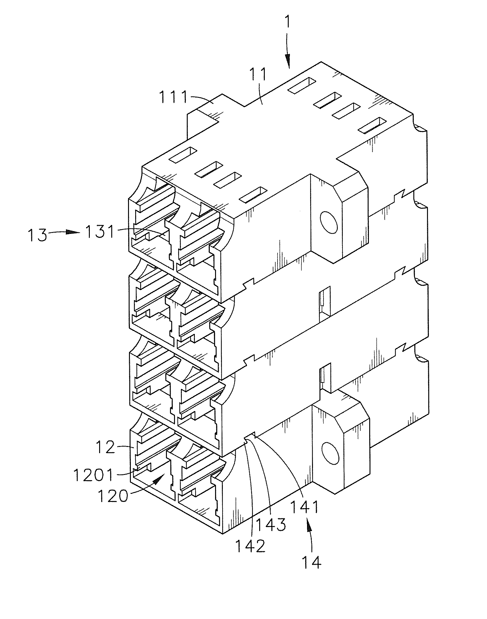
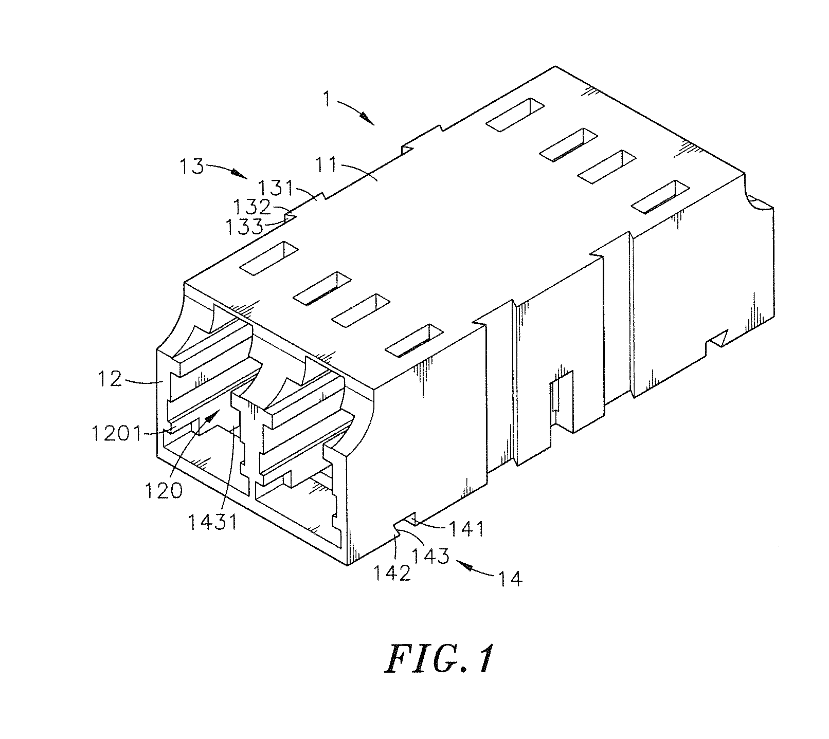
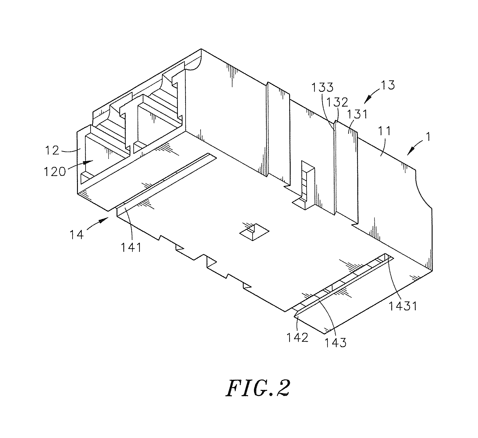
[0027]Reference will now be made in detail to the exemplary embodiments of the present disclosure, examples of which are illustrated in the accompanying drawings. Therefore, it is to be understood that the foregoing is illustrative of exemplary embodiments and is not to be construed as limited to the specific embodiments disclosed, and that modifications to the disclosed exemplary embodiments, as well as other exemplary embodiments, are intended to be included within the scope of the appended claims. These embodiments are provided so that this disclosure will be thorough and complete, and will fully convey the inventive concept to those skilled in the art. The relative proportions and ratios of elements in the drawings may be exaggerated or diminished in size for the sake of clarity and convenience in the drawings, and such arbitrary proportions are only illustrative and not limiting in any way. The same reference numbers are used in the drawings and the description to refer to the ...


PUM


Abstract

The present disclosure provides a stackable optical fiber adapter including shell members, a base with mating parts formed at front and rear sides thereof, and an accommodating cavity being transversely formed therein and communicated with the two opposite mating parts. One positioning part and wedged-jointing part are at two adjacent bases, and one clasping block and position-limiting groove are on the positioning part and the wedged-jointing part. By such a way, each two adjacent bases can be stacked, arranged or formed by a modularized manner, so that more shell members can be installed on a panel. The adapter can be easy to design the corresponding mold, the mating parts of each shell member is constant, and necessary to develop different molds, so the manufacturing process and the mold can be simplified, and the optical fiber adapter of the present disclosure can have stable structure and low cost, and further facilitate mass production.

Description

REFERENCE TO RELATED APPLICATIONS[0001]This application claims the priority benefit of U.S. Provisional patent application No. 61 / 998,933, filed on Jul. 14, 2014, currently pending.BACKGROUND OF THE INVENTION[0002]1. Field of the Invention[0003]The present disclosure relates to an optical fiber adapter and more particularly, to a stackable optical fiber adapter, and each two adjacent bases of a plurality of shell members of the stackable optical fiber adapters can be vertically stacked, horizontally arranged in parallel or assembled in an array structure by a modularized manner to form as an integral assembly by cooperation between a positioning part and a wedged-jointing part, so that more shell members can be installed on the panel with higher density, and effects of stable structure, easy mass production and lower cost can be achieved.[0004]2. Description of the Related Art[0005]In recent years, with rapid development in communication technology and internet, data center venders ...

Claims


Application Information

Patent Timeline
Patent Type & Authority Applications(United States)
IPC IPC(8): G02B6/38
CPCG02B6/3825G02B6/3897
Inventor LEE, JHIH-PINGLEE, WEI-CHENG
Owner CORNING OPTICAL COMM LLC
Why Eureka
Try Eureka