Wireless power transmission device

a power transmission device and wireless technology, applied in the direction of battery data exchange, circuit arrangement, inductance, etc., can solve the problems of fixed detection accuracy not being maintained when used, inability to maintain the same detection accuracy for the power supply area, and inability to maintain the same detection accuracy. , to achieve the effect of the same accuracy

Active Publication Date: 2016-01-14
PANASONIC INTELLECTUAL PROPERTY MANAGEMENT CO LTD
View PDF1 Cites 35 Cited by
  • Summary
  • Abstract
  • Description
  • Claims
  • Application Information

AI Technical Summary

Benefits of technology

[0013]The wireless power transmission device according to the present invention allows the same accuracy for detecting metal or an electric appliance to be maintained regardless of product differences between circuit elements, wear over time, and changes in the usage environment.

Problems solved by technology

Such variations are caused by product differences resulting from product variations (manufacturing variations), wear over time, the usage environment (temperature), and the like.
However, this is not taken into consideration in the wireless power supplying devices of the prior art.
Thus, the manufactured wireless power transmission devices cannot all be maintained with the same detection accuracy.
Thus, a fixed detection accuracy cannot be maintained when used over a long period or when the usage environment (temperature etc.) changes.
Thus, the same detection accuracy cannot be maintained for the power supplying areas.

Method used


Image

  • Wireless power transmission device
  • Wireless power transmission device
  • Wireless power transmission device

Examples


Embodiment Construction

[0026]One embodiment of a wireless power transmission device will now be described with reference to the drawings.

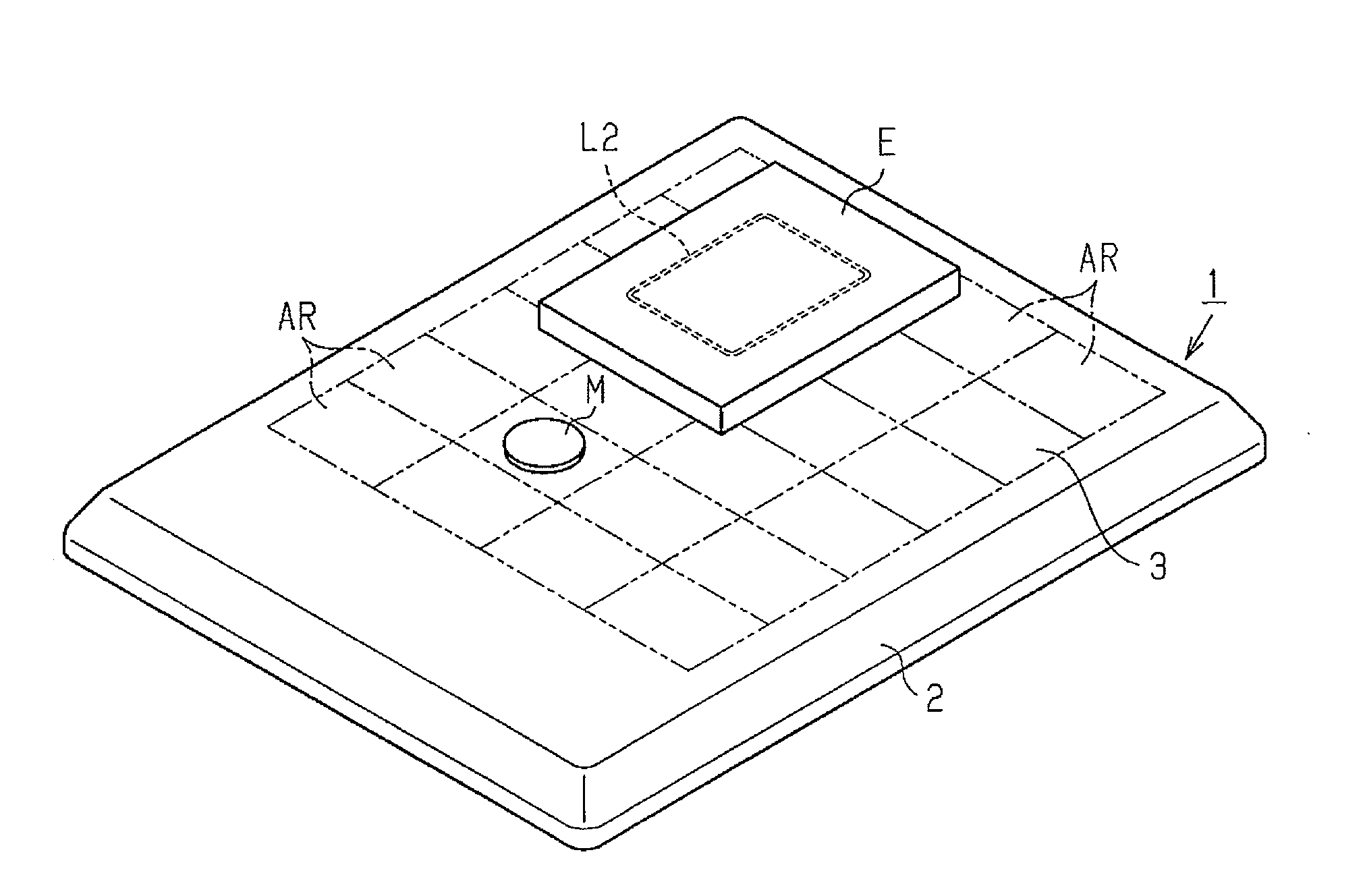
[0027]FIG. 1 is a perspective view showing a wireless power transmission device (hereinafter referred to as the power supplying device) 1 and an electric appliance (hereinafter referred to as the appliance) E, which is supplied with power from the power supplying device 1 through wireless connection.

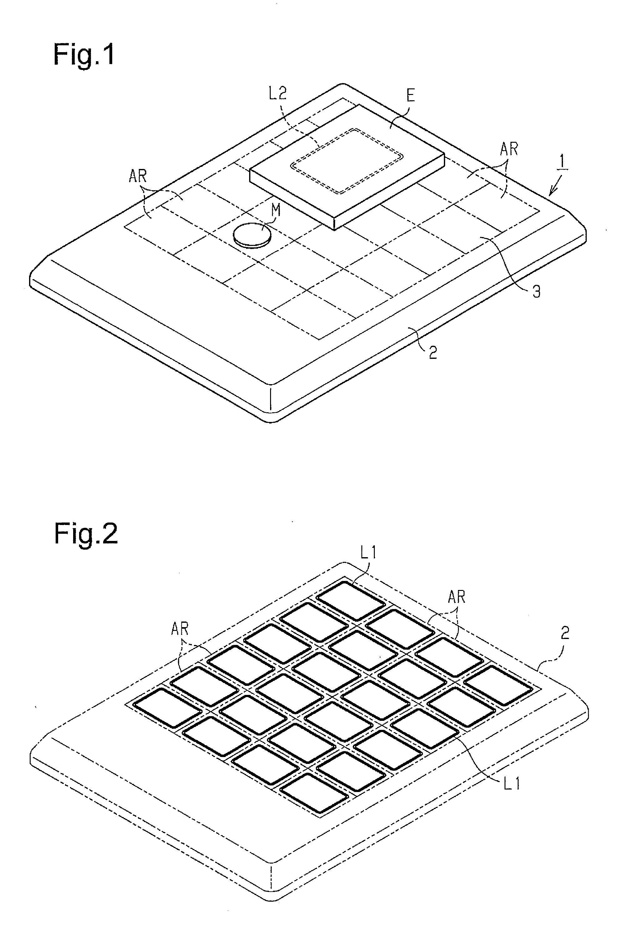
[0028]The power supplying device 1 includes a housing 2, which is tetragonal and generally plate-shaped. The housing 2 includes a setting surface 3 on which the appliance E is set. The setting surface 3 is a flat surface. The setting surface 3 is divided into, for example, a plurality of tetragonal power supplying areas AR. In the present embodiment, twenty-four power supplying areas AT are laid out in four columns (in the sideward direction) and six rows (in the longitudinal direction).

[0029]As shown in FIG. 2, a primary coil L1 is arranged at a location corresponding to eac...


PUM


Abstract

A wireless power transmission device includes a detection coil and a capacitor that configure a resonance circuit. An oscillation circuit generates high-frequency current corresponding to a detection frequency for performing presence detection of an electric appliance and metal. A presence detection circuit performs presence detection of the electric appliance and the metal based on an output voltage obtained by exciting the detection coil with the high-frequency current having the detection frequency. A detection condition changing circuit performs an initial value setting mode that changes a detection condition of the presence detection circuit in accordance with a resonance characteristic. The detection condition changing circuit includes a detection frequency changing circuit that changes the detection frequency in accordance with the resonance characteristic.

Description

TECHNICAL FIELD[0001]The present invention relates to a wireless power transmission device.BACKGROUND ART[0002]As one type of a wireless power transmission device, patent document 1 discloses a wireless power supplying device that detects displacement of an electric appliance, which is a power supplying subject, from the power factor of power supplied from a primary resonance circuit. The power supplying device adjusts the characteristics of the primary resonance circuit based on the power factor to limit decreases in the power supplying efficiency when displacement occurs.[0003]In the power supplying device, if a power supplying operation is performed when there is a foreign matter, the foreign matter may be heated. It is thus desirable that such a foreign matter be detected to stop the power supplying operation.[0004]Patent document 2 discloses a wireless power supplying device that includes a detection coil for detecting metal in addition to a primary coil for supplying power. Th...

Claims


Application Information

Patent Timeline
Patent Type & Authority Applications(United States)
IPC IPC(8): H02J5/00
CPCH02J5/005H02J50/12H02J50/90H02J7/00045H02J50/402H02J50/60H02J50/80
Inventor KOHARA, HIROSHIOZAKI, MAMORUTSUJIMOTO, TOYOHIKO
Owner PANASONIC INTELLECTUAL PROPERTY MANAGEMENT CO LTD
Why Eureka
Try Eureka