Motor Control

Active Publication Date: 2016-01-14
TRW LIMITED
View PDF3 Cites 5 Cited by
  • Summary
  • Abstract
  • Description
  • Claims
  • Application Information

AI Technical Summary

Benefits of technology

[0019]The demand signal may have a value representative of the torque that is to be produced by the motor. Alternatively, the demand signal may comprise a current demand signal having a value representative of current expressed in a rotating d-q frame that rotates with the motor rotor. The d-q current demand signal will in effect be representative of the torque demanded of the motor, albeit expressed as a current. The downsampling of the present invention may be applied to the torque demand signal prior to any conversion to the d-q axis current reference.

Problems solved by technology

The applicant has gone further to appreciate that noise in the demand signal can be a cause of this noise and this is often due to errors in the output signal from the torque sensor.

Method used


Image

  • Motor Control
  • Motor Control
  • Motor Control

Examples


Embodiment Construction

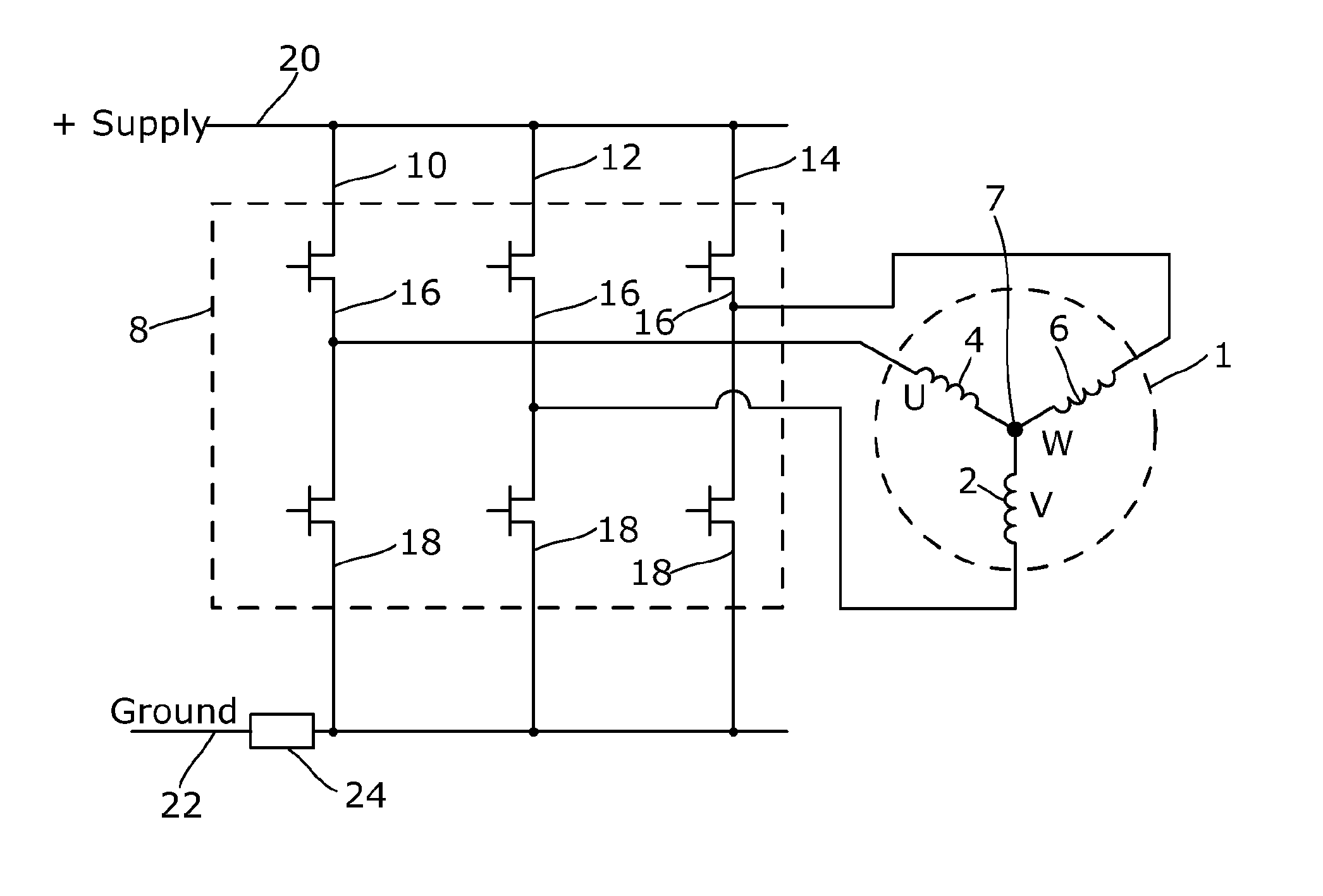
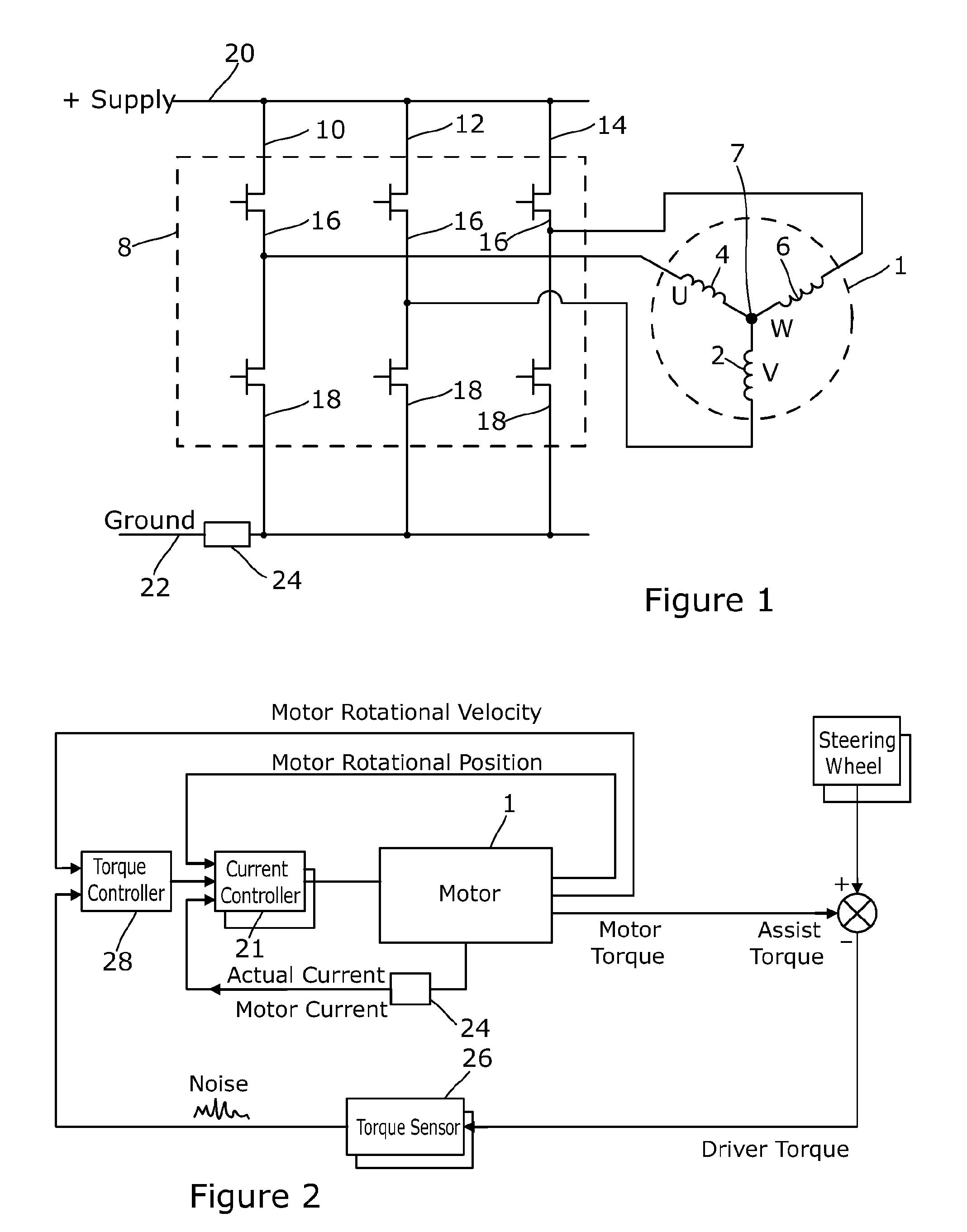
[0043]Referring to FIG. 1 a three phase brushless motor 1 comprises three motor windings 2, 4, 6, generally designated as phases A, B and C, connected in a star network. One end of each coil is connected to a respective terminal. The other ends of the coils are connected together to form the star centre 7. The free ends are connected to a switching circuit arranged as an H-bridge.

[0044]The switching circuit comprises a three phase bridge 8, one for each phase of the motor. Each arm 10, 12, 14 of the bridge comprises a pair of switches in the form of a top transistor 16 and a bottom transistor 18 connected in series between a supply rail 20 and ground line 22. The motor windings 2, 4, 6 are each tapped off from between a respective complementary pair of transistors 16, 18.

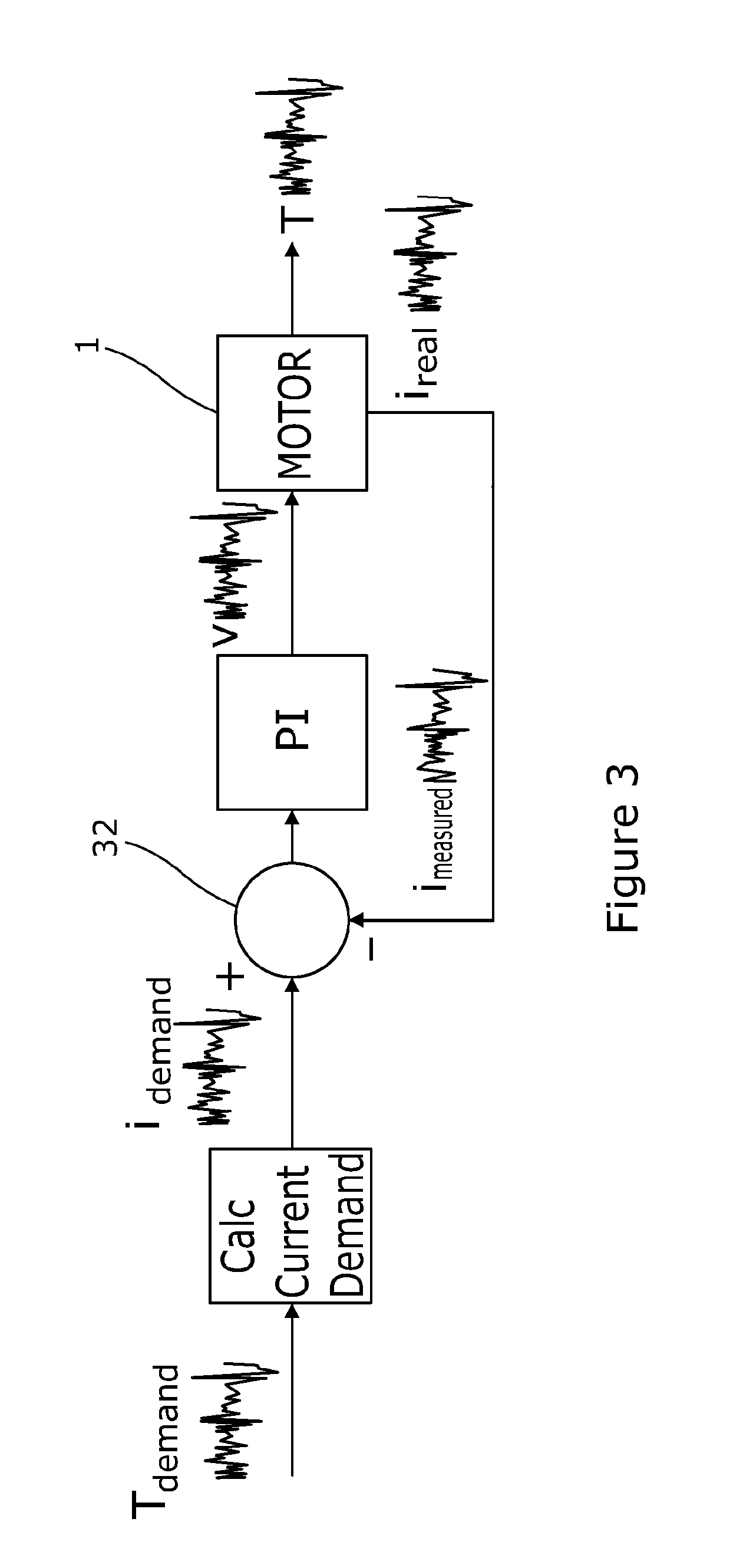
[0045]The transistors 16, 18 are turned on and off in a controlled manner by a motor controller 21, which is shown in detail in FIG. 3 of the drawings, to provide pulse width modulation of the potential applied to e...


PUM


Abstract

A motor drive circuit comprises a motor having a plurality of phases, a switching circuit comprising a plurality of electrical switches, a motor current controller that generates voltage demand signals to be passed to a drive circuit for the switches that in turn generate pulse width modulated switching signals for the switching circuit that cause the switches to selectively connect the phases to a power supply so as to cause current to flow through the phases of the motor, and a motor torque controller that produces a demand signal that is fed to an input of the current controller, the motor current controller responding to an error signal that is at least partially dependent on the value of the demand signal. The torque controller in use updates the demand signal at a first sample rate. The motor drive circuit further comprises a downsampling circuit that in use modifies the demand signal under certain operating conditions so that the demand signal is only updated at a second sample rate that is lower than the first rate.

Description

CROSS-REFERENCE TO RELATED APPLICATIONS[0001]This application is a national stage of International Application No. PCT / GB2014 / 050668 filed Mar. 6, 2014, the disclosures of which are incorporated herein by reference in entirety, and which claimed priority to Great Britain Patent Application No. 1304156.1 filed Mar. 7, 2013, the disclosures of which are incorporated herein by reference in entirety.BACKGROUND OF THE INVENTION[0002]This invention relates to improvements in motor control circuits, and in particular to pulse width modulation (PWM) control of multiple phase brushless motors in electric power assisted steering systems.[0003]Control systems for PWM controlled electric motors, especially DC motors, generally need to measure the current flowing through the windings or phases of the motor and this can either be done by means of separate current sensors for each of the phases, or by means of a single current sensor that is placed in the circuit so as to measure the total instant...

Claims


Application Information

Patent Timeline
Patent Type & Authority Applications(United States)
IPC IPC(8): H02P7/06
CPCH02P7/06H02P23/03B62D5/046
Inventor PRAHLAD, NIKHIL
Owner TRW LIMITED
Why Eureka
Try Eureka