Electrical architecture for an aircraft, an aircraft, and a method of using it

a technology of aircraft and electric architecture, applied in the field of aircraft, can solve problems such as negative influence on the weight breakdown of aircraft, and achieve the effect of reducing the problem

Active Publication Date: 2016-01-21
EUROCOPTER
View PDF1 Cites 29 Cited by
  • Summary
  • Abstract
  • Description
  • Claims
  • Application Information

AI Technical Summary

Benefits of technology

[0027]An object of the present invention is to provid

Problems solved by technology

Except during stages in which the electrical member is operating, such converters represent

Method used


Image

  • Electrical architecture for an aircraft, an aircraft, and a method of using it
  • Electrical architecture for an aircraft, an aircraft, and a method of using it
  • Electrical architecture for an aircraft, an aircraft, and a method of using it

Examples


Embodiment Construction

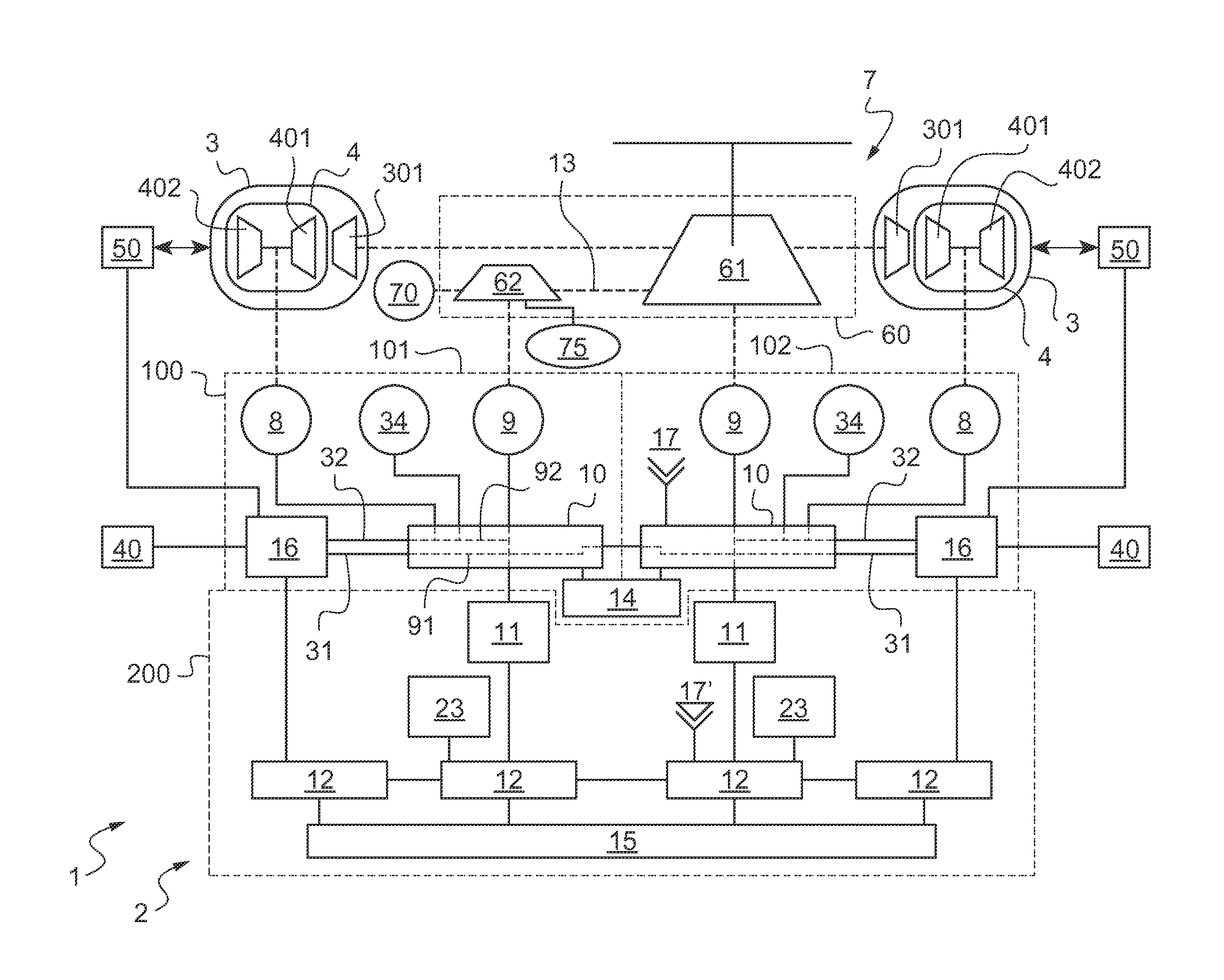
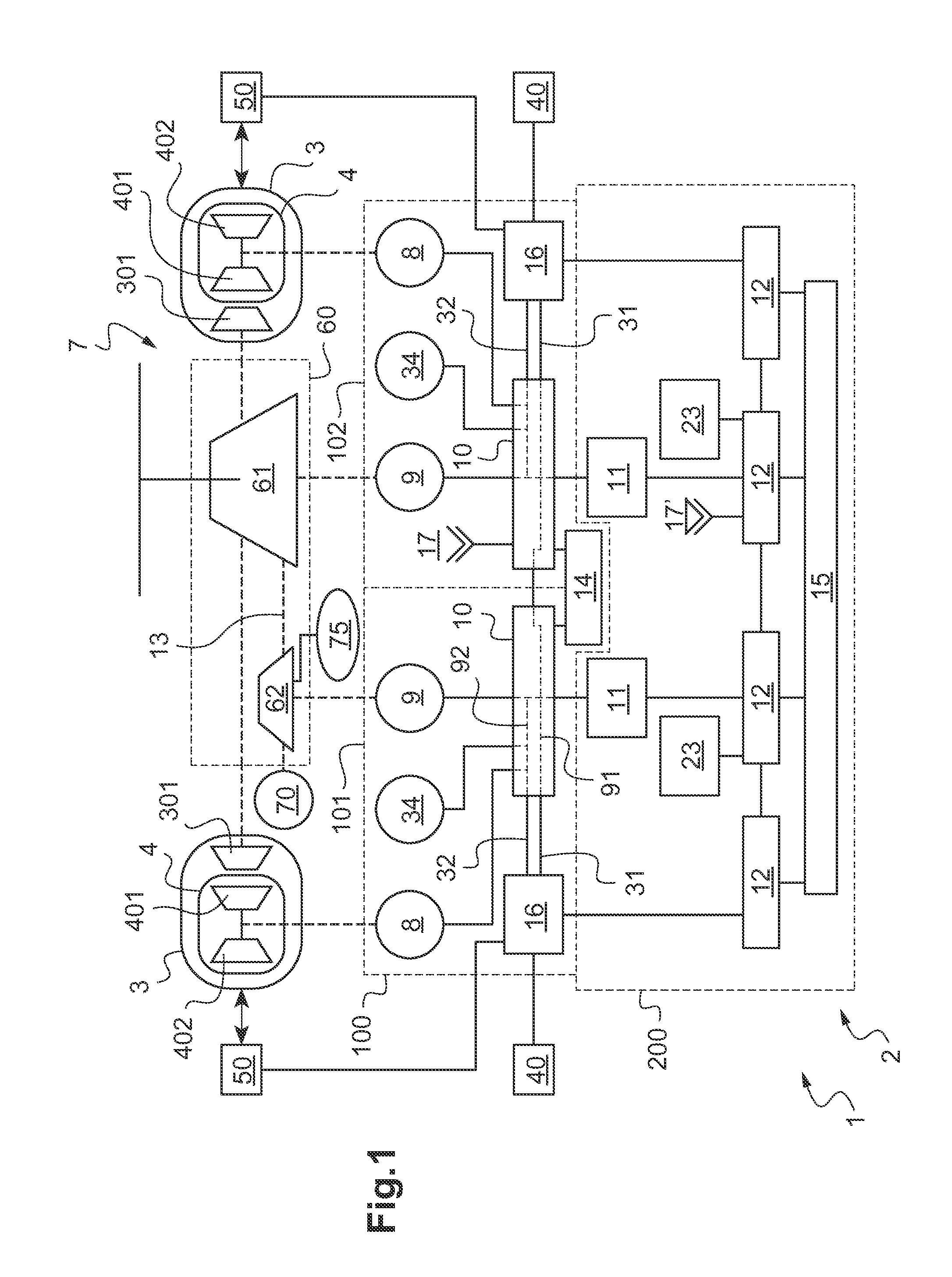
[0116]FIG. 1 shows an aircraft 1. By way of example, this aircraft is a rotorcraft having at least one lift rotor 7. Under such circumstances, the lift rotor 7 contributes to providing the aircraft 1 with at least some of its lift, and possibly also contributes to its propulsion.

[0117]The aircraft has a power plant in particular for driving the lift rotor in rotation.

[0118]The power plant has at least one fuel burning engine 3 driving a power transmission assembly 60.

[0119]Such a fuel burning engine 3 may be a turboshaft engine having a gas generator 4. The gas generator 4 is then conventionally provided with at least one compression stage 402 connected to a high pressure turbine 401. The turboshaft engine may also have at least one free turbine stage 301 that is secured to an outlet shaft, which is generally connected indirectly to the power transmission assembly 60. For example, each outlet shaft may be connected to the power transmission assembly 60 via a drive train including a ...


PUM


Abstract

An electrical architecture for an aircraft having a main electrical machine connected to a fuel burning engine and a secondary electrical machine connected to a power transmission assembly. A high-voltage electrical master box is connected by a first line and by a second line to a multifunction converter, the high-voltage electrical master box connecting the first line to the secondary electrical machine, and the second line to at least the main electrical machine and the secondary electrical machine. The multifunction converter includes a supervisor connected to an avionics system and to a control system controlling the engine, and to a controller of the high-voltage electrical master box.

Description

CROSS REFERENCE TO RELATED APPLICATION[0001]This application claims priority to French patent application No. FR 14 01593 filed on Jul. 17, 2014, the disclosure of which is incorporated in its entirety by reference herein.BACKGROUND OF THE INVENTION[0002]1. Field of the Invention[0003]The present invention relates to an electrical architecture for an aircraft, to an aircraft, and to a method performed by the electrical architecture.[0004]The present invention thus relates to the field of aircraft, and in particular aircraft having a rotary wing. More particularly, the invention relates to aircraft having a so-called “hybrid” power plant for driving rotation of at least one rotor of a rotary wing via a main power transmission gearbox of the aircraft. Such a main power transmission gearbox is referred to more simply below as the “power transmission gearbox”.[0005]2. Description of Related Art[0006]A “hybrid” power plant designates a power plant comprising at least one fuel burning eng...

Claims


Application Information

Patent Timeline
IPC IPC(8): B64D35/02B64D27/24
CPCB64D35/02Y10S903/904B64D2027/026B64D27/24B64D27/10B64D31/14B64D35/08B64D2221/00Y02T50/60
Inventor SAUTREUIL, MATTHIEUBEZES, GILLES
Owner EUROCOPTER
Why Eureka
Try Eureka