
Integrated smo gas sensor module

a gas sensor and module technology, applied in the field of microelectronic sensors, can solve the problems of smo sensors having difficulty distinguishing between two gases, smo sensors may have difficulty in quickly draining the battery of portable sensor devices, and smo sensors can be heated to temperatures in the range of 100 c-400 c, so as to save battery power, reduce power consumption, and accurate temperature measurements

Active Publication Date: 2016-01-21
STMICROELECTRONICS PTE LTD
View PDF4 Cites 24 Cited by
  • Summary
  • Abstract
  • Description
  • Claims
  • Application Information

AI Technical Summary

Benefits of technology

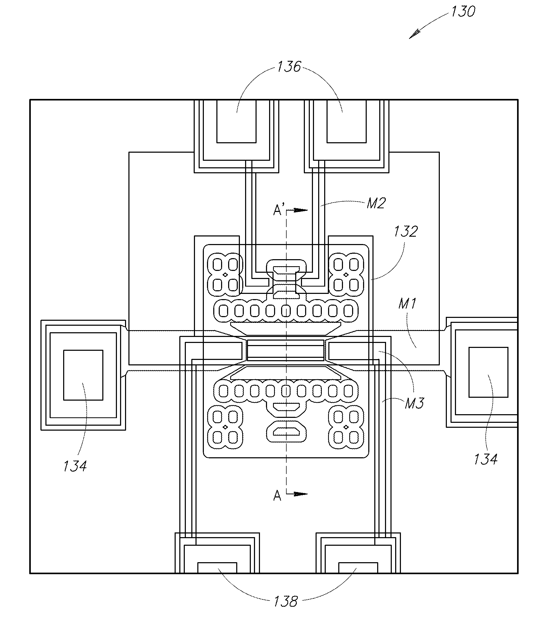
The patent describes a method of making a small gas sensor module that can be integrated with an ASIC, which is a type of semiconductor device. This integration results in a more efficient and less noisy gas sensor because the sensor is closer to the ASIC, reducing the need for wiring and power dissipation. The gas sensor module can detect different gas species by using dedicated sensors or by thermally tuning the sensors to monitor specific gas species. Overall, the method allows for more accurate and efficient gas sensing.

Problems solved by technology

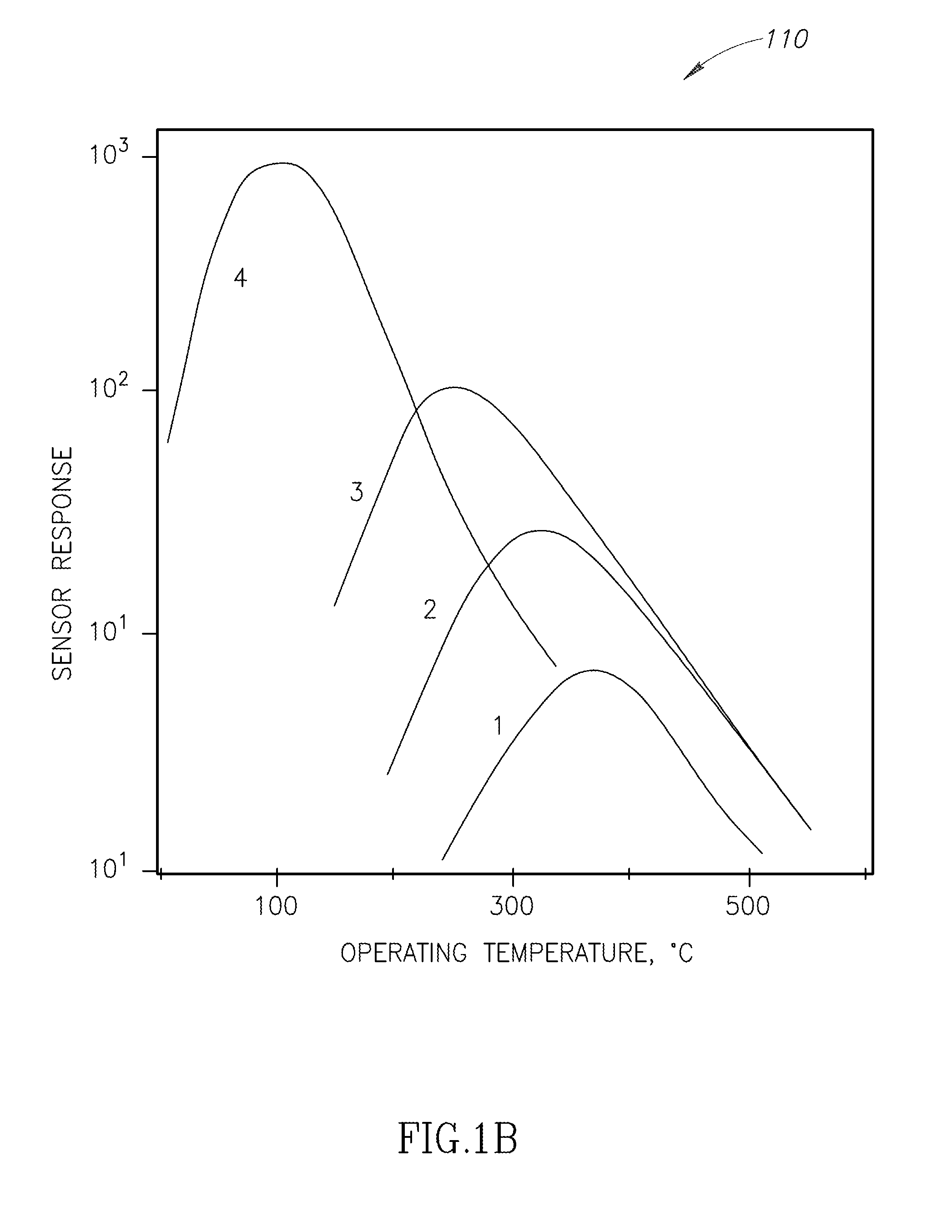
One problem that arises in designing SMO thin film gas sensors is that the associated heaters tend to consume large amounts of electrical power to heat the SMO thin films to operating temperatures in the range of about 100 C-500 C, so the heaters tend to quickly drain the battery of the portable sensor device.
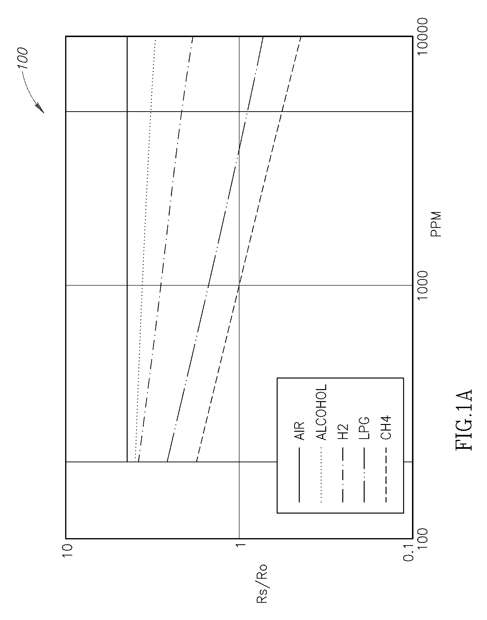
Another challenge is that the SMO sensors may have difficulty distinguishing between two gases.
Another challenge lies in providing thermal insulation for the gas sensors so that neighboring devices are not heat-damaged by such extreme temperatures.
In some environments, heating the SMO sensor to temperatures in the range of 100 C-400 C can pose a safety risk—for example, if there exists a sufficient concentration of an ambient gas for which the combustion temperature is within the range of the operating temperature of the sensor.
However, although air is an effective thermal insulator, a substrate having an air cavity is generally structurally unstable, and prone to collapse.
Thus, the depth of such an air cavity may be structurally limited.

Method used


Image

  • Integrated smo gas sensor module
  • Integrated smo gas sensor module
  • Integrated smo gas sensor module

Examples


Embodiment Construction

[0029]In the following description, certain specific details are set forth in order to provide a thorough understanding of various aspects of the disclosed subject matter. However, the disclosed subject matter may be practiced without these specific details. In some instances, well-known structures and methods of semiconductor processing comprising embodiments of the subject matter disclosed herein have not been described in detail to avoid obscuring the descriptions of other aspects of the present disclosure.

[0030]Unless the context requires otherwise, throughout the specification and claims that follow, the word “comprise” and variations thereof, such as “comprises” and “comprising” are to be construed in an open, inclusive sense, that is, as “including, but not limited to.”

[0031]Reference throughout the specification to “one embodiment” or “an embodiment” means that a particular feature, structure, or characteristic described in connection with the embodiment is included in at le...


PUM


Abstract

Miniature resistive gas detectors incorporate thin films that can selectively identify specific gases when heated to certain characteristic temperatures. A solid state gas sensor module is disclosed that includes a gas sensor, a heater, and a temperature sensor, stacked over an insulating recess. The insulating recess is partially filled with a support material that provides structural integrity. The solid state gas sensor module can be integrated on top of an ASIC on a common substrate. With sufficient thermal insulation, such a gas detector can be provided as a low-power component of mobile electronic devices such as smart phones. A method of operating a multi-sensor array allows detection of relative concentrations of different gas species by either using dedicated sensors, or by thermally tuning the sensors to monitor different gas species.

Description

BACKGROUND[0001]1. Technical Field[0002]The present disclosure generally relates to the field of microelectronic sensors and, in particular, gas sensors integrated with circuitry on a semiconductor substrate.[0003]2. Description of the Related Art[0004]Miniature solid state gas sensors integrated with microelectronics allow construction of an “electronic nose” that can selectively detect the presence of, for example, toxic substances such as carbon monoxide (CO), or vapor associated with controlled substances such as ethanol.[0005]It is well known that thin films made of certain metal materials, for example, semiconductor metal oxides (SMOs), experience a change in resistivity when they are exposed to certain gases at certain temperatures, as described in U.S. Pat. No. 4,485,667. Typically, SMO sensors operate at temperatures between 200 and 500 C. One such example of an SMO material is tin oxide (SnO2) which, when heated to 380 C-400 C and then exposed to methane gas, experiences a...

Claims


Application Information

Patent Timeline
IPC IPC(8): G01N27/406
CPCG01N27/4065G01N27/12G01N27/123G01N27/125G01N27/128G01N27/129G01N27/227
Inventor SHANKAR, RAVILE NEEL, OLIVIERLOH, TIEN-CHOYKAM, SHIAN-YEU
Owner STMICROELECTRONICS PTE LTD
Learn More