Crystal vibration device

a crystallized and vibration device technology, applied in piezoelectric/electrostrictive/magnetostrictive devices, piezoelectric/electrostriction/magnetostriction machines, electrical equipment, etc., can solve the problems of affecting the quality of crystallized vibration, unable to obtain excellent vibration characteristics with certainty, etc., to achieve effective suppression of the degradation of crystallized characteristic and excellent characteristics

Active Publication Date: 2016-01-28
MURATA MFG CO LTD
View PDF1 Cites 4 Cited by
  • Summary
  • Abstract
  • Description
  • Claims
  • Application Information

AI Technical Summary

Benefits of technology

[0016]With the crystal vibration device according to the present invention, since the distance A is given a specific range, degradation of the ESR characteristic can be effectively suppressed. Therefore, a crystal vibration device having excellent characteristics can be provided.

Problems solved by technology

In the piezoelectric device described in Patent Document 2, there is a risk that the vibration will be damped depending on the coating state of the conductive adhesive bonding the crystal unit.
In other words, excellent vibration characteristics cannot be obtained with certainty.

Method used


Image

  • Crystal vibration device
  • Crystal vibration device
  • Crystal vibration device

Examples


Embodiment Construction

[0023]Hereafter, the present invention will be made clearer by describing specific embodiments of the present invention while referring to the drawings.

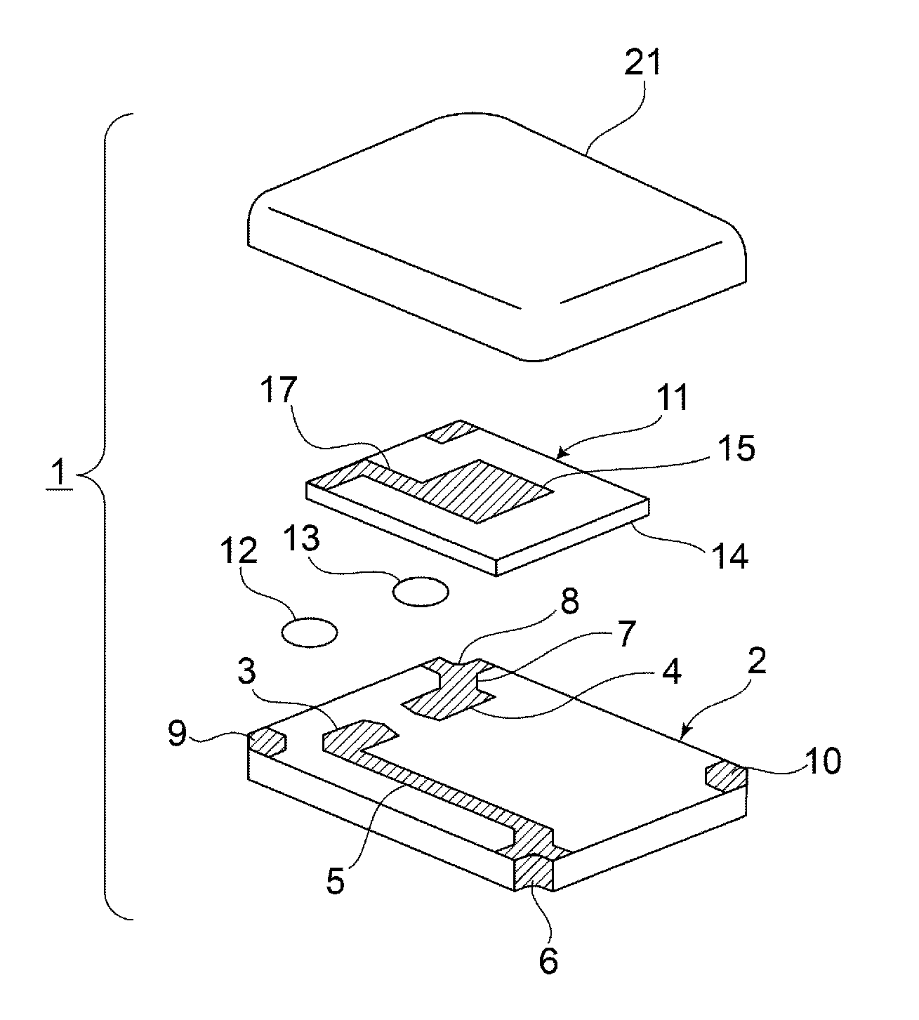
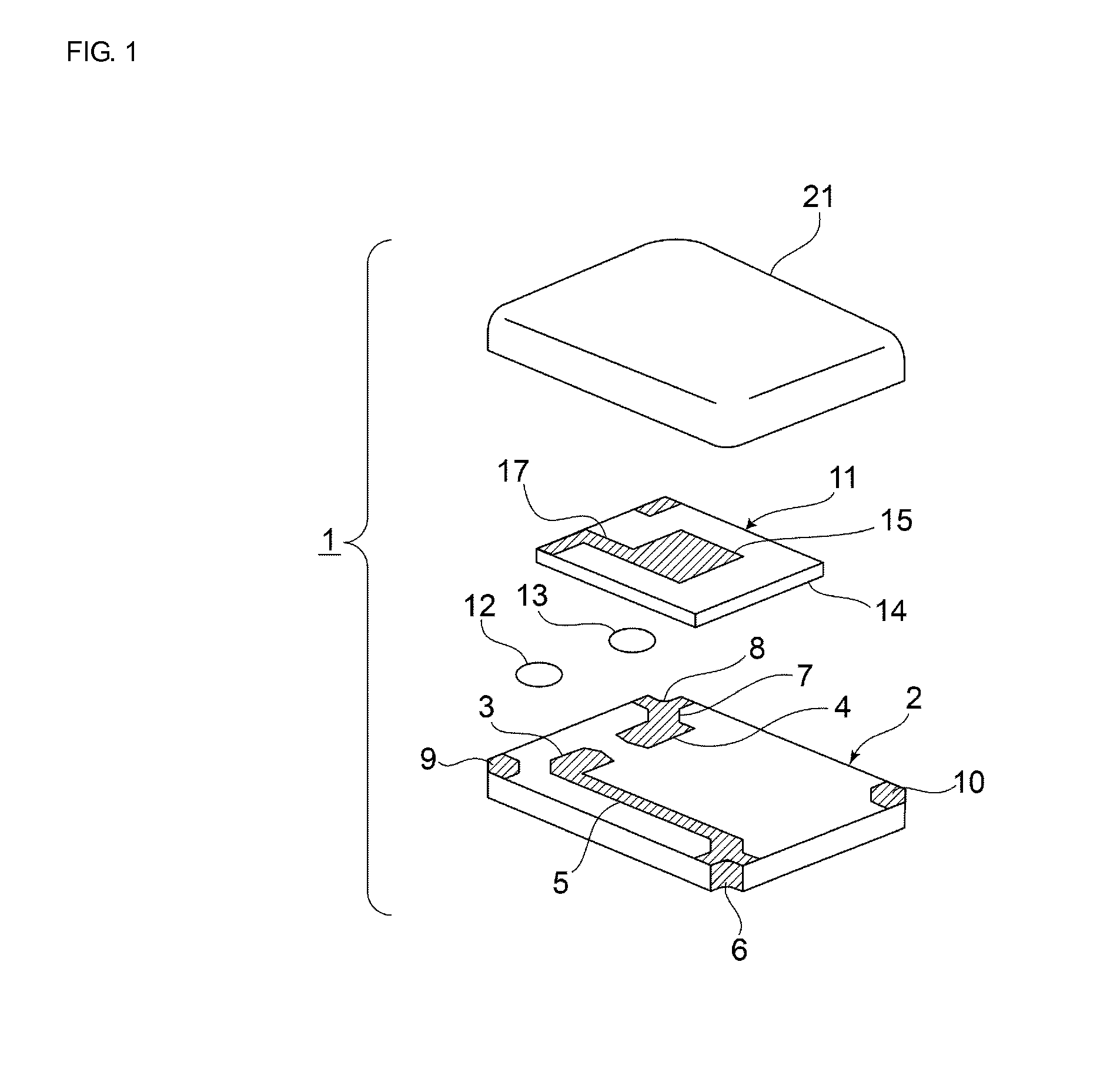
[0024]FIG. 1 is an exploded perspective view of a crystal vibration device according to an embodiment of the present invention. A crystal vibration device 1 includes a case substrate 2. The case substrate 2 is composed of a suitable insulating material. As examples of such an insulating material, an insulating ceramic such as alumina and a synthetic resin can be given. In this embodiment, the case substrate 2 is composed of alumina.

[0025]First and second mounting electrodes 3 and 4 are formed on an upper surface of the case substrate 2. The first mounting electrode 3 is led out to one corner portion of the case substrate 2 by a wiring electrode 5. A first outer electrode 6 is formed in part of that corner portion. The first outer electrode 6 is attached to an inner peripheral surface of a concavity provided by cutting away part of th...


PUM


Abstract

A crystal vibration device where a crystal unit is supported on a case substrate in a cantilever manner by first and second conductive adhesive layers. The crystal unit has a length direction and is formed using a rectangular-plate-shaped crystal substrate and A>4.30t+0.16, where A (mm) represents a shorter distance among distances between a central axis of the crystal substrate and end portions of the first and second conductive adhesive layers on a central axis side, and t (μm) represents a thickness of the crystal substrate.

Description

CROSS REFERENCE TO RELATED APPLICATIONS[0001]The present application is a continuation of International application No. PCT / JP2014 / 057802, filed Mar. 20, 2014, which claims priority to Japanese Patent Application No. 2013-080301, filed Apr. 8, 2013, the entire contents of each of which are incorporated herein by reference.FIELD OF THE INVENTION[0002]The present invention relates to crystal vibration devices employing a crystal unit and particularly relates to crystal vibration devices in which a crystal unit is mounted on a case substrate using a conductive adhesive.BACKGROUND OF THE INVENTION[0003]Conventionally, crystal vibration devices employing a crystal unit are widely used in resonators and so forth. For example, a piezoelectric device in which a crystal unit is supported in a cantilever manner on a base substrate is disclosed in below-listed Patent Document 1. The crystal unit is formed using an AT cut crystal vibration element in which a thickness shear vibration is a main ...

Claims


Application Information

Patent Timeline
Patent Type & Authority Applications(United States)
IPC IPC(8): H01L41/053H01L41/047
CPCH01L41/0472H01L41/053H03H9/19H03H9/02157H03H9/0509H03H9/1021H10N30/88H10N30/872
Inventor YAMAMOTO, HIROYUKIASAI, MASARU
Owner MURATA MFG CO LTD
Why Eureka
Try Eureka