Electrically heated catalyst device

a catalyst device and catalyst technology, applied in the direction of engines, mechanical equipment, machines/engines, etc., can solve the problems of reducing application and temperature difference between the carrier and the electric diffusion layer, and achieve the effects of reducing thermal stress, reducing thermal stress, and reducing cracks

Active Publication Date: 2016-02-04
TOYOTA JIDOSHA KK
View PDF3 Cites 16 Cited by
  • Summary
  • Abstract
  • Description
  • Claims
  • Application Information

AI Technical Summary

Benefits of technology

[0011]In the electrically heated catalyst device according to the aspect of the present invention, since the electric diffusion layer is formed so as to be divided into a plurality of regions in the axial direction of the carrier, in an ON time of current application to the carrier, current concentration to a central part of the electric diffusion layer is dispersed. As a result, a temperature difference between the carrier and the electric diffusion layer in an OFF time of the current application is decreased, which decreases a thermal stress caused therebetween. Accordingly, it is possible to restrain an occurrence of cracks in the carrier due to heat cycles.
[0012]The carrier and the electric diffusion layers may contain SiC. Further, the electrically heated catalyst device may further includes a controller configured to control the current application to the carrier, each of the electric diffusion layers may be formed so as to be divided into two regions in the axial direction of the carrier. The wiring member fixed to the two regions may be formed so as to be divided electrically from each other. Two electric circuits may be provided, and in each of the two electric circuits, two regions of the electric diffusion layers which are diagonally opposed to each other via the carrier may be electrically connected to each other. The controller may alternately apply a current to the two electric circuits. With such a configuration, it is possible to further more effectively restrain an occurrence of cracks in the carrier due to heat cycles.
[0013]According to the present invention, it is possible to provide an electrically heated catalyst device in which an occurrence of cracks in a carrier due to heat cycles is restrained.

Problems solved by technology

As a result, a temperature difference between the carrier and the electric diffusion layer in an OFF time of the current application is decreased, which decreases a thermal stress caused therebetween.

Method used


Image

  • Electrically heated catalyst device
  • Electrically heated catalyst device
  • Electrically heated catalyst device

Examples


first embodiment

Modification of First Embodiment

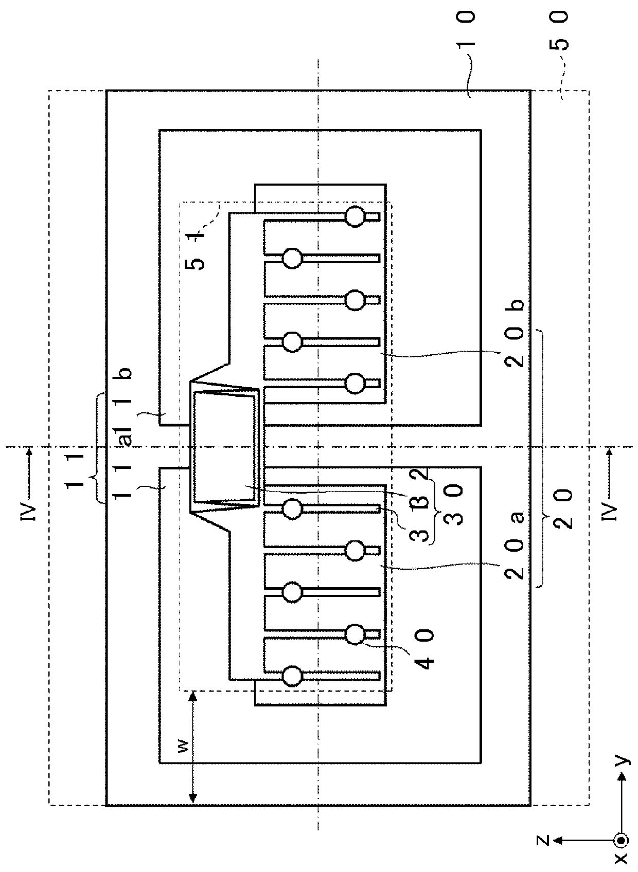
[0050]Next will be described an electrically heated catalyst device according to a modification of the first embodiment, with reference to FIG. 5. FIG. 5 is a plan view of the electrically heated catalyst device according to the modification of the first embodiment. FIG. 5 corresponds to FIG. 3. As illustrated in

[0051]FIG. 5, in the electrically heated catalyst device according to the modification of the first embodiment, an electric diffusion layer 11 is divided into four regions, i.e., a first region 11a, a second region 11b, a third region 11c, and a fourth region 11d. A first region 20a, a second region 20b, a third region 20c, and a fourth region 20d of a surface electrode 20 are formed, respectively, on the first region 11a, the second region 11b, the third region 11c, and the fourth region 11d of the electric diffusion layer 11. Further, two comb-shaped wiring lines 31 are provided in each of the regions of the surface electrode 20.

[0052]In the...

second embodiment

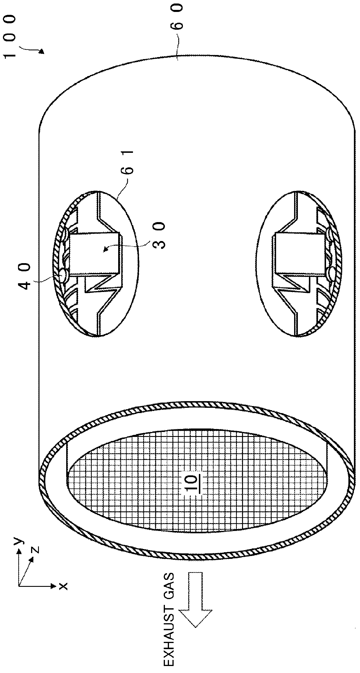
[0053]Next will be described an electrically heated catalyst device according to a second embodiment with reference to FIG. 6. FIG. 6 is a perspective view of the electrically heated catalyst device according to the second embodiment. FIG. 6 corresponds to FIG. 2. As illustrated in FIG. 6, in the electrically heated catalyst device according to the second embodiment, first wiring members 30a are formed on respective first regions 20a of surface electrodes 20, and second wiring members 30b are formed on respective second region 20b of the surface electrodes 20. That is, wiring members 30 are each formed so as to be physically and electronically divided into the first wiring member 30a and the second wiring member 30b. Here, the first wiring members 30a are placed so as to be opposed to each other via a carrier 10. Further, the second wiring members 30b are placed so as to be opposed to each other via the carrier 10.

[0054]As illustrated in FIG. 6, a leading portion 32a of the first wi...


PUM


Abstract

An electrically heated catalyst device includes: a carrier configured to carry a catalyst; a pair of electric diffusion layers formed on an outer peripheral surface of the carrier so as to be opposed each other; and wiring members each fixed to each of the electric diffusion layers, and the carrier is electrically heated via the wiring members. Each of the electric diffusion layers is formed so as to be divided into a plurality of regions in an axial direction of the carrier.

Description

INCORPORATION BY REFERENCE[0001]The disclosure of Japanese Patent Application No. 2014-153973 filed on Jul. 29, 2014 including the specification, drawings and abstract is incorporated herein by reference in its entirety.BACKGROUND OF THE INVENTION[0002]1. Field of the Invention[0003]The present invention relates to an electrically heated catalyst device.[0004]2. Description of Related Art[0005]In recent years, an electrically heated catalyst (EHC) device has attracted attention as an exhaust gas purifier that purifies exhaust gas discharged from an engine of an automobile or the like. In the EHC, even under a condition in which a temperature of the exhaust gas is low and a catalyst is hard to be activated like just after engine start, it is possible to forcibly activate the catalyst by electrical heating and to raise purification efficiency of the exhaust gas.[0006]In an EHC described in Japanese Patent Application Publication No. 2013-136997 (JP 2013-136997 A), an outer peripheral ...

Claims


Application Information

Patent Timeline
Patent Type & Authority Applications(United States)
IPC IPC(8): F01N3/20
CPCF01N3/2013F01N3/2026F01N3/2828F01N13/18Y02T10/12
Inventor SUGIYAMA, NATSUKINAITO, HIDEJI
Owner TOYOTA JIDOSHA KK
Why Eureka
Try Eureka