Fano resonance microwave spectroscopy of high absorption matter

a high-absorption matter and microwave spectroscopy technology, applied in the field of microwave spectroscopy, can solve the problems of inability to clearly interpret data, inability to properly correlate measured parameters with structural characteristics of chemical and biological objects in microwaves, and inability to define and separate regions with maximum magnetic (electric) field and null electric (magnetic) field

Inactive Publication Date: 2016-02-04
B G NEGEV TECH & APPL LTD
View PDF2 Cites 6 Cited by
  • Summary
  • Abstract
  • Description
  • Claims
  • Application Information

AI Technical Summary

Benefits of technology

[0036]In embodiments of the apparatus of the second aspect of the invention the dielectric sample is a liquid enclosed in a small capsule.
[0037]In embodiments of the apparatus of the second aspect of the invention the dielectric sample is a liquid that continuously flows through the rectangular waveguide microwave cavity via a small diameter tube. These embodiments additionally comprise a pump, a reservoir and a main line that are connected together to continuously circulate the liquid through the small diameter tube.

Problems solved by technology

Study of microwave properties of biological liquids is one of the most important problems in biophysics.
The success of a spectroscopic technique depends on two main problems: one is the availability of accurate data over the required frequency range while the other is the ability to unambiguously interpret this data.
Spatially, regions with maximum magnetic (electric) field and null electric (magnetic) field can no longer be well defined and separated.
Proper correlation of the measured parameters with structural characteristics of chemical and biological objects in microwaves appears as a serious problem.
The resonant techniques, however, are not suitable for high-lossy liquids because the resonance peak is so broad that the perturbation characteristics cannot be measured correctly.
Also, interpretation of the data obtained from the transmission / reflection technique cannot be considered as sufficiently suitable for high-lossy liquids.
It appears, however, that such representation of parameters and, moreover, interpretation that these data properly characterize high-lossy materials may be beyond a physical meaning.
Only with this limitation, the perturbation technique permits linkage via a simple formula between changes in the resonant frequency and loaded factor determined by the sample.
For high-lossy materials, the cavity resonance curve becomes so wide that evaluation of the quality-factor shift cannot presume exact evaluation of the frequency shift.
Moreover, since the cavity resonance curve is wide, other resonances (originated, for example, from the terminal connectors) become prominent and an accurate detection of the resonant frequency shift appears to be very difficult.

Method used


Image

  • Fano resonance microwave spectroscopy of high absorption matter
  • Fano resonance microwave spectroscopy of high absorption matter
  • Fano resonance microwave spectroscopy of high absorption matter

Examples


experiment 1

[0079

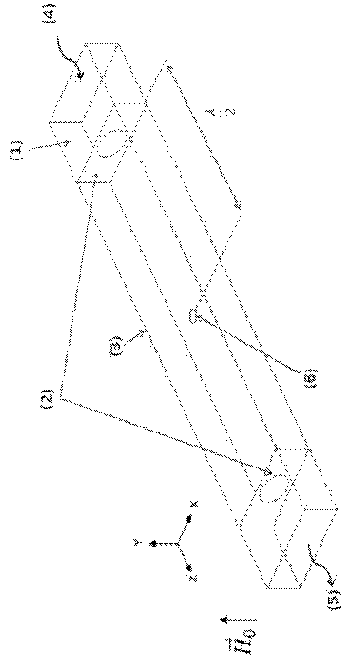
[0080]The first experiment does not demonstrate the invention but is a demonstration of the above mentioned problems of the material characterization by using a standard perturbation technique. Without a bias magnetic field {right arrow over (H)}0, a ferrite disk behaves as a small dielectric sample. Since a ferrite disk is placed in a maximum of the cavity RF magnetic field, its role (when {right arrow over (H)}0=0) is negligibly small. FIG. 3a shows the frequency characteristics of a transmission coefficient when the cavity 3 is loaded with a small low-loss dielectric sample 7 (S21 is a parameter of the scattering matrix). The samples measured were air (∈r=1) and two ceramics disks having diameters of 3 mm and thickness of 2 m and dielectric constants ∈r=30 (K-30; TCI Cermics, Inc.) and ∈r=50 (K-30; TCI Cermics, Inc.). For such dielectric samples, the cavity is highly coherent and other “parasitic” scattering channels are less dominant, making the standard perturbation techni...

experiment 2

[0083

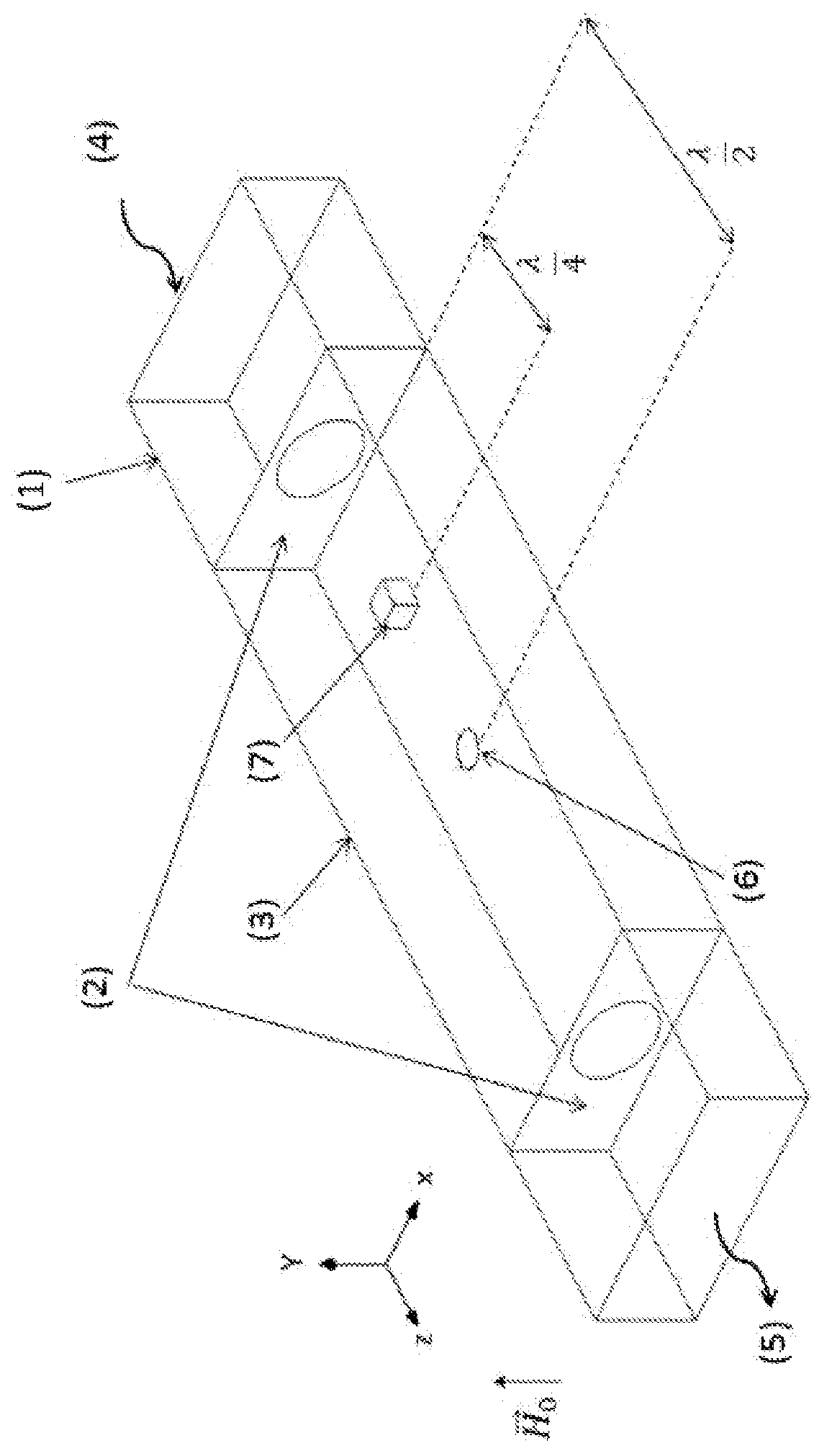
[0084]This experiment illustrates how the Fano-interference method of the invention can be used to detect the cavity resonance frequency when the cavity is loaded by a high-lossy material. FIG. 4b shows the experimental setup. In this case the sample is comprised of high-lossy wrapping material 8 shown symbolically surrounding air 10. A variable bias magnetic field, shown symbolically by the border 11 surrounding disk 6, is applied to the ferrite disk 6.

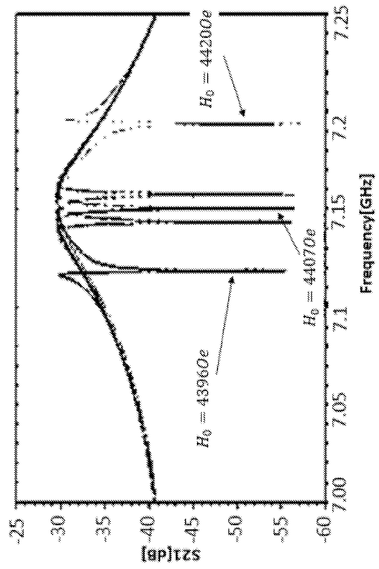
[0085]When a suitable bias magnetic field is switched on, the MDM spectral peaks of a ferrite disk are observed. FIG. 4a shows the positions of the main MDM peaks for different values of the bias magnetic field. It can be seen clearly that for magnetic field values {right arrow over (H)}0(1) and {right arrow over (H)}0(2) the same type of the peak line-shape that corresponds to the Fano asymmetry parameter q>0 is obtained.

[0086]While for a bias field {right arrow over (H)}0(4) there is another type of the peak line-shape with th...

experiment 3

[0088

[0089]The purpose of this experiment is to show that by using the method of the invention different spectroscopic Lorentz-peak markers on the frequency axis are obtained for different materials. FIG. 5c schematically shows the experimental setup used for this experiment. It is essentially the same as FIG. 4b with the exception that the high loss wrapping material 9 (polyurethane) surrounds one of the two dielectric samples 8 (∈r=30; εr=50) used in experiment 1 in addition to an air sample 10. The samples are placed in a maximum of the RF electric field of the cavity. For {right arrow over (H)}0=0 the frequency characteristics of a transmission coefficient in the cavity are shown in FIG. 3b. When a bias magnetic magnetic field is switched on, these characteristics remains generally the same, but sharp MDM peaks additionally appear as can be seen in FIG. 5a. With variation of the bias field a Lorentz-peak bias field is obtained for every type of a high-lossy material sample. The ...


PUM

PropertyMeasurementUnit
Fano resonance microwave spectroscopyaaaaaaaaaa
magnetic-dipolar-modeaaaaaaaaaa
MDM resonance frequencyaaaaaaaaaa

Abstract

The invention is a method of Fano resonance microwave spectroscopy of high absorption matter. The method comprises: embedding a magnetic-dipolar-mode (MDM) ferrite disk in the microwave cavity, loading a sample of the high absorption matter in the microwave cavity, using a bias magnetic field to tune the MDM resonance frequency of the ferrite disk to the resonance frequency of the cavity; and observing the symmetric Lorentz-like lineshape of the resonance peaks that are obtained.

Description

FIELD OF THE INVENTION[0001]The invention is from the field of microwave spectroscopy. Specifically the invention relates to microwave spectroscopy characterization of lossy materials including biological liquids.BACKGROUND OF THE INVENTION[0002]Publications and other reference materials referred to herein are numerically referenced in the following text and respectively grouped in the appended Bibliography which immediately precedes the claims.[0003]Fano resonances arise when two transmission pathways, a broad band continuum and a narrow band resonance, interfere with each other [1]. When one of the channels is a highly damped resonance process, its exact resonant frequency is difficult to detect and such a channel can be considered as a broad band continuum. The physical origin of Fano resonances can be understood simply from the dynamics of a system of coupled oscillators. The Fano-resonant phenomenon appears as a notch in the absorption spectrum when the incident electromagnetic...

Claims


Application Information

Patent Timeline
Patent Type & Authority Applications(United States)
IPC IPC(8): G01N22/00
CPCG01N22/00
Inventor VAISMAN, GUYELMAN, EVGENYHOLLANDER, ELADKAMENETSKII, EUGENE O.SHAVIT, REUVEN
Owner B G NEGEV TECH & APPL LTD
Why Eureka
Try Eureka