
Composite electrode for flow battery

a flow battery and composite technology, applied in the direction of fuel cells, cell components, indirect fuel cells, etc., can solve the problems of high compression, reducing efficiency, reducing efficiency, and leaking electrolyte through the flow frame, so as to reduce feed pressure, reduce pressure drop, and reduce the effect of compressibility

Inactive Publication Date: 2016-02-04
CONCURRENT TECH
View PDF9 Cites 21 Cited by
  • Summary
  • Abstract
  • Description
  • Claims
  • Application Information

AI Technical Summary

Benefits of technology

The present invention is abouta new composite electrode for flow batteries that has a unique structure. The electrode is made of a combination of carbon felt and foam, which is either in a layered form or created through 3D printing. This new electrode design reduces the need for high compression, which can lower the pressure drop across the electrodes and improve the efficiency and performance of flow batteries. The carbon foam also provides better electrical conductivity. This patent aims to provide an electrode that can operate with lower feed pressures, experience less pressure drop, and have improved electrical resistivity.

Problems solved by technology

Use of carbon felt as the electrodes for the flow battery system, however, poses several problems.
High compression tends to generate bulging and alignment issues when assembling the cell stacks.
Consequently, yielding efficient electrical properties requires high pressure pumping, but expending energy to do so results in reduced efficiency.
Operating at higher pumping pressures also tends to lead to leakage of electrolyte through the flow frame as well.

Method used


Image

  • Composite electrode for flow battery
  • Composite electrode for flow battery

Examples


Embodiment Construction

[0020]The following description is of an embodiment presently contemplated for carrying out the present invention. This description is not to be taken in a limiting sense, but is made merely for the purpose of describing the general principles and features of the present invention. The scope of the present invention should be determined with reference to the claims.

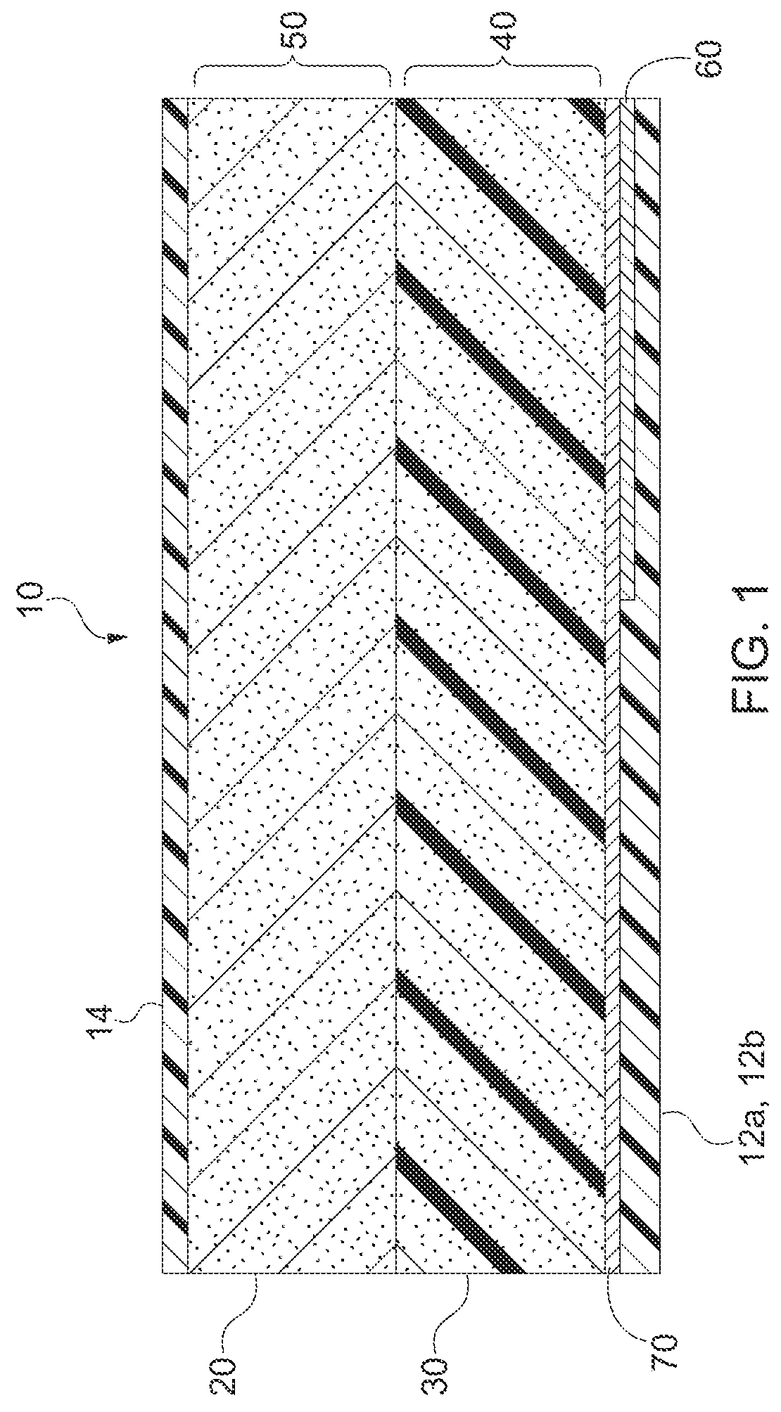
[0021]Referring now to FIG. 1, a cross-sectional schematic of the composite electrode 10, in accordance with a preferred embodiment, is disclosed. The composite electrode 10 includes a composition of carbon felt 20 and carbon foam 30. This composite electrode 10 can be manufactured as two or more laminated layers or as a single piece through additive manufacturing or other manufacturing techniques. The carbon felt 20 is preferably carbon electrode felt from the SGL Group. The carbon foam 30 is preferably Duecel® reticulated vitreous foam provided by ERG Aerospace. Of course, one skilled in the art will appreciate that oth...


PUM

PropertyMeasurementUnit
electrically conductiveaaaaaaaaaa
poresaaaaaaaaaa
chemical potentialaaaaaaaaaa

Abstract

A composite electrode adapted for use in a flow battery stack system has a carbon felt stratum forming a semi-porous reaction zone and a carbon foam stratum forming a porous flow path zone. The composite electrode is less compressible than prior art electrodes having similar conductivity and specific surface areas. Flow battery stack systems employing the composite electrode operate with lower feed pressures, experiences a lower pressure drops across the electrodes, and realize improved electrical resistivity. Alternative embodiments provide electrical conductive elements and a current collector disposed on a surface of the composite electrode.

Description

CROSS-REFERENCE TO RELATED APPLICATIONS[0001]This patent application claims the benefit of co-pending U.S. Provisional Patent Application No. 62 / 030,722, filed on Jul. 30, 2014, which is hereby incorporated by reference in its entirety.FIELD OF THE INVENTION[0002]The present invention is directed generally towards an electrode having a composite construction and, more particularly, to an electrode having a carbon felt stratum forming a semi-porous reaction zone and a carbon foam stratum forming a porous flow path zone.BACKGROUND OF THE INVENTION[0003]A flow battery system is a rechargeable fuel cell exploiting the fluid dynamics, kinetics, and chemical potential properties of fluids containing electroactive elements (i.e., electrolytes) to convert chemical energy to electrical energy. The electrolytes typically comprise a catholyte fluid and an anolyte fluid, where each are stored in separate electrolyte tanks. At least one pump for each tank, directs the electrolytes from the elect...

Claims


Application Information

Patent Timeline
Patent Type & Authority Applications(United States)
IPC IPC(8): H01M4/86H01M8/18H01M8/20
CPCH01M4/8657H01M4/8605H01M8/20H01M8/188Y02E60/50
Inventor BREZOVEC, PAUL JOHNKENNEDY, TIMOTHY ALLENMCCLUSKEY, MICHEL J.MARKIEWICZ, DANIEL R.
Owner CONCURRENT TECH
Learn More