Insulation-type synchronous dc/dc converter

a synchronous, dc/dc technology, applied in the direction of electric variable regulation, process and machine control, instruments, etc., can solve the problem of no protection function for abnormal conditions on the secondary sid

Active Publication Date: 2016-02-04
ROHM CO LTD
View PDF6 Cites 44 Cited by
  • Summary
  • Abstract
  • Description
  • Claims
  • Application Information

AI Technical Summary

Benefits of technology

[0014]The present invention has been made in order to solve such a problem. Accordingly, it is an exemplary purpose of the present invention to provide a DC / DC converter with functions for detecting the secondary side abnormality and for protecting the circuit in the abnormal condition.
[0016]With such an embodiment, by integrating the abnormal detection circuit with the feedback circuit having the error amplifier, the abnormal condition in the secondary side of the DC / DC converter can be detected. When the abnormal condition is detected, the protection circuit invalidates the voltage feedback with the error amplifier and the duty ratio of the switching transistor is decreased. Then power supplied to the secondary side is reduced and the circuit is protected. Further, instead of the shunt regulator configured as a discrete device, the error amplifier integrated on a semiconductor chip allows to reduce a power consumption.
[0022]Such an embodiment allows to maintain the voltage at the photo coupler connection terminal over the zener voltage of the diode regardless of the feedback condition or the abnormal condition, and the internal power supply voltage can be stabilized.
[0025]With such an embodiment, by integrating the abnormal detection circuit and the error amplifier on the synchronous rectifier controller, the abnormal condition in the secondary side of the DC / DC converter can be detected. When the abnormal condition is detected, the protection circuit invalidates the voltage feedback with the error amplifier and the duty ratio of the switching transistor is decreased. Then a power supplied to the secondary side is reduced and the circuit is protected. Further, instead of the shunt regulator configured as a discrete device, the error amplifier integrated on a semiconductor chip allows to reduce a power consumption.

Problems solved by technology

However, the circuit in FIG. 1 has no function for detecting the abnormal condition in the secondary side, and there is no protection function for the abnormal condition in the secondary side.

Method used


Image

  • Insulation-type synchronous dc/dc converter
  • Insulation-type synchronous dc/dc converter
  • Insulation-type synchronous dc/dc converter

Examples


first embodiment

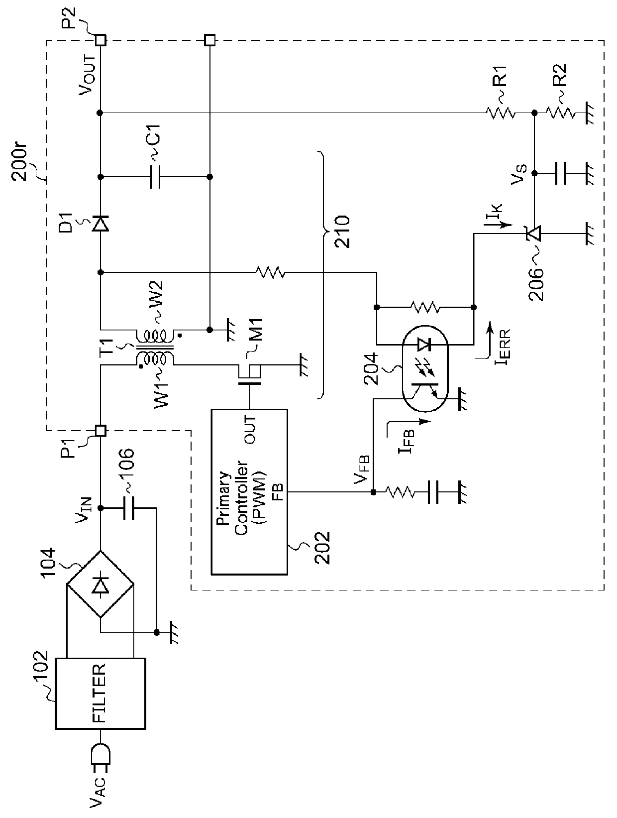
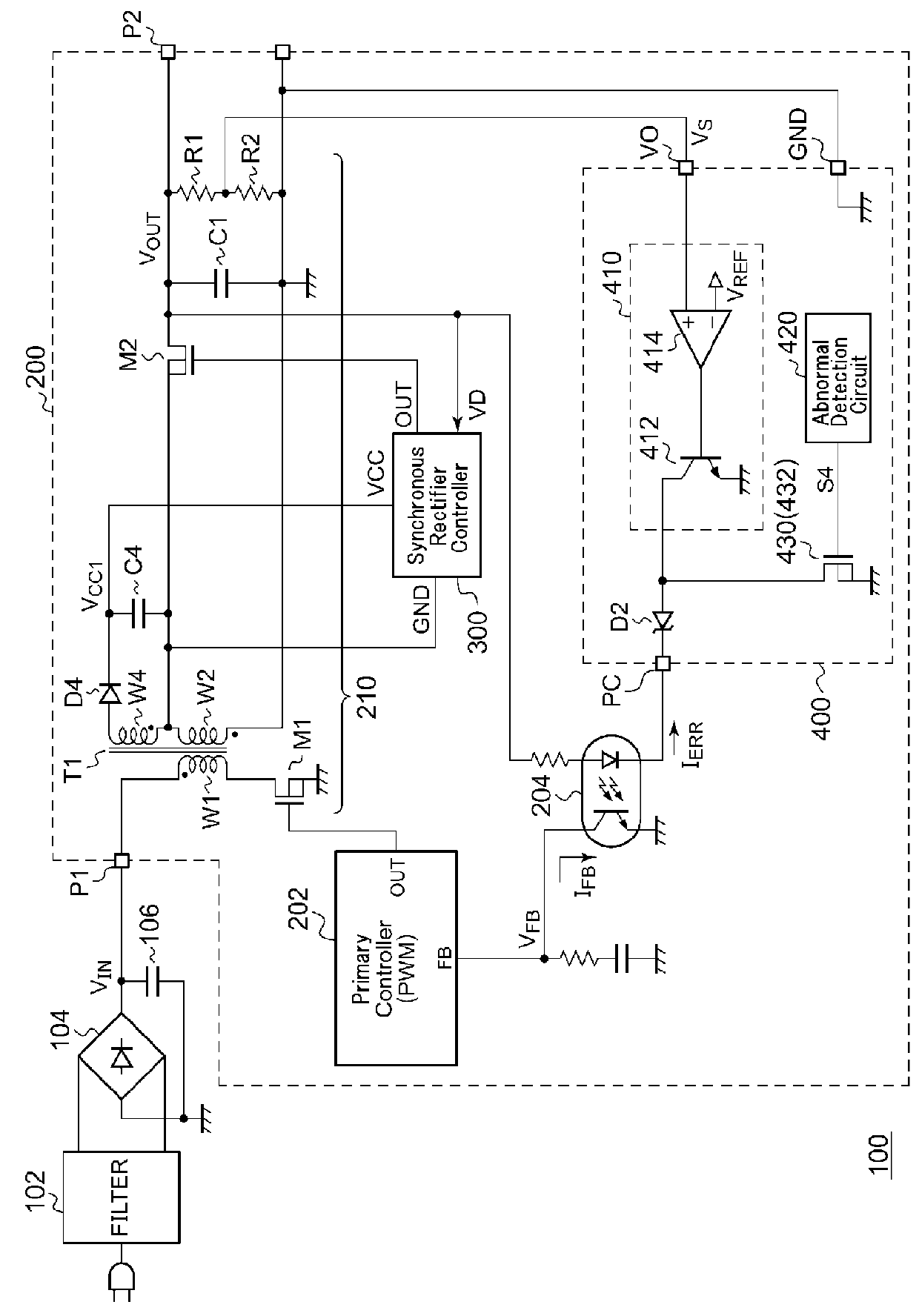
[0054]FIG. 2 is a circuit diagram of an AC / DC converter 100 according to a first embodiment. The AC / DC converter 100 includes a filter 102, a rectifier circuit 104, a smoothing capacitor 106, and an insulation-type DC / DC converter 200.

[0055]The DC / DC converter 200 includes a primary controller 202, a photo coupler 204, an output circuit 210, and a synchronous rectifier controller 300. The output circuit 210 has a topology of a synchronous flyback converter, and includes a transformer T1, a switching transistor M1 coupled to a primary winding W1, a synchronous rectifier transistor M2 coupled to a secondary winding W2, and an output capacitor C1. In this embodiment, the synchronous rectifier transistor M2 is provided at a higher voltage side of the secondary winding of the transformer T1 (output terminal P2 side).

[0056]An auxiliary winding W4 of the transformer T1, a diode D4 and a capacitor C4 generate an external power supply voltage VCC1 with reference to the source of the synchron...

second embodiment

[0088]FIG. 5 is circuit diagram of an AC / DC converter 100a according to a second embodiment. In the second embodiment, the feedback IC 400 of FIG. 4 is integrated in the synchronous rectifier controller 300a.

[0089]The synchronous rectifier controller 300a includes a driver circuit 302, an error amplifier 410, an OCP circuit 440, an abnormal detection circuit 420, and a protection circuit 430.

[0090]The synchronous rectifier transistor M2 is inserted at lower voltage side (ground side) of the secondary winding W2, and the power supply terminal of the synchronous rectifier controller 300a is supplied with the output voltage VOUT of the DC / DC converter 200a. The ground terminal of the synchronous rectifier controller 300a is coupled to the ground line of the DC / DC converter 200a.

[0091]The second embodiment provides the same advantage of the first embodiment by integrating the error amplifier 410 and the abnormal detection circuit 420 in the synchronous rectifier controller 300a.

Modif...

third embodiment

[0093]FIG. 6 is a circuit diagram of an AC / DC converter 100b according to a third embodiment. The synchronous rectifier transistor M2 is provided at the higher voltage side of the secondary winding W2 of the transformer T1.

[0094]The synchronous rectifier controller 300b includes a driver circuit 302b, an error amplifier 410, an abnormal detection circuit 420, a protection circuit 430 and an internal regulator 450. The synchronous rectifier controller 300b may further includes an OCP circuit 440. The configurations and the operations of these components are described above.

[0095]In the third embodiment, a power supply plane of the driver circuit 302b and a power supply plane of the other circuit blocks are isolated each other, and the ground planes are also isolated. For example, the driver circuit 302d is integrated on the first semiconductor chip (die), and the diode D2, the error amplifier 410, the abnormal detection circuit 420, the protection circuit 430, the OCP circuit 440 and...


PUM


Abstract

The feedback IC is provided at the secondary side of the DC / DC converter and is coupled to the photo coupler. The error amplifier amplifies an error between a voltage detection signal according to an output voltage of the DC / DC converter and a target voltage, and draws a current according to the error from the input side of the feedback photo coupler via the photo coupler connection terminal. The abnormal detection circuit asserts an abnormal detection signal when an abnormal condition in a secondary side of the DC / DC converter is detected. The protection circuit is coupled to the photo coupler connection terminal, and acts on the feedback photo coupler via the photo coupler connection terminal so that a feedback operation by the error amplifier is invalid and an on-period of the switching transistor is shorten.

Description

[0001]This application is based upon and claims the benefit of priority from the prior Japanese Patent Application No. 2014-158075, filed Aug. 1, 2014 and Japanese Patent Application No. 2015-108898, filed May 28, 2015, the entire contents of which are incorporated herein by reference.BACKGROUND OF THE INVENTION[0002]1. Field of the Invention[0003]The present invention relates to a DC / DC converter.[0004]2. Description of the Related Art[0005]Various kinds of home appliances such as TVs, refrigerators etc., each receive externally applied commercial AC electric power for its operation. Also, electronic devices such as laptop computers, cellular phone terminals, and tablet devices are each configured to operate using commercial AC electric power, and / or to be capable of charging a built-in battery using the commercial AC electric power. Such home appliances and electronic devices (which will collectively be referred to as “electronic devices” hereafter) each include a built-in power s...

Claims


Application Information

Patent Timeline
Patent Type & Authority Applications(United States)
IPC IPC(8): H02M3/335
CPCH02M3/33592H02M1/32H02M1/0025Y02B70/10
Inventor KIKUCHI, HIROKISHIMIZU, RYO
Owner ROHM CO LTD
Why Eureka
Try Eureka