High efficiency coherent imager

a coherent imager and high-efficiency technology, applied in the field of optical detection, can solve the problems of only being able to achieve efficient heterodyne detection, heterodyne detection is not easy to achieve, and the efficiency of the system is reduced, so as to reduce the effectiveness of the system

Active Publication Date: 2016-02-04
BAE SYST INFORMATION & ELECTRONICS SYST INTERGRATION INC
View PDF4 Cites 5 Cited by
  • Summary
  • Abstract
  • Description
  • Claims
  • Application Information

AI Technical Summary

Benefits of technology

[0008]Currently, heterodyne detection has two significant limitations. First, efficient heterodyne detection has typically only been possible for point sources. For example, a given system may allow detection of a single field point in order to determine properties of that point, such as for three dimensional shape measurements. Thus, present systems only accomplish heterodyne detection for single point sources, and not over a large field of view. A second weakness of current heterodyne systems is due to resultant astigmatisms, interference fringes, aberrations and / or other optical flaws that reduce the effectiveness of the system. Such optical flaws are a result of system design and configuration. In these respects, heterodyne detection has heretofore been limited in its utility.

Problems solved by technology

Currently, heterodyne detection has two significant limitations.
First, efficient heterodyne detection has typically only been possible for point sources.
Thus, present systems only accomplish heterodyne detection for single point sources, and not over a large field of view.
A second weakness of current heterodyne systems is due to resultant astigmatisms, interference fringes, aberrations and / or other optical flaws that reduce the effectiveness of the system.
Such optical flaws are a result of system design and configuration.
In these respects, heterodyne detection has heretofore been limited in its utility.
Issues continue to exist with limitations in heterodyne detection.
For instance, one exemplary problem with the apparatus identified in U.S. Pat. No. 7,561,813 is that the local oscillator beam, that is combined with the signal beam, is collimated, whereas the signal beam is focused onto the detector with a convergent beam.

Method used


Image

  • High efficiency coherent imager
  • High efficiency coherent imager
  • High efficiency coherent imager

Examples


Embodiment Construction

[0018]As a further background, the prior art known before this disclosure for a direct or conventional optical detection process involves the conversion of photons into a detection signal (usually measured in charge carriers, current, or voltage) inside an electronic square-law detector, which produces a signal that is proportional to the square of the incoming electric field. In this prior art process, the phase information of the incoming signal is altogether lost, once the signal beam enters the detection medium, which may be a photomultiplier tube, a PIN photo-diode, or, for imaging applications, a CID or CCD detector array.

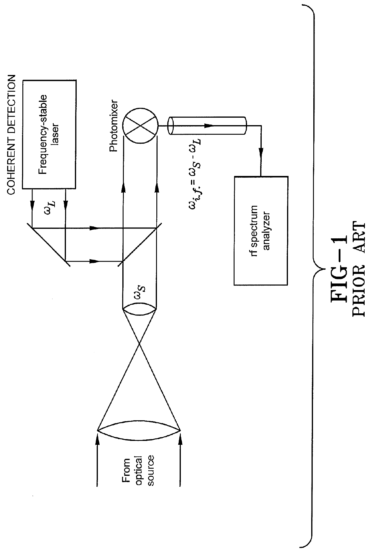
[0019]As depicted in FIG. 1, the prior art provides, in contrast to the statements immediately above, a coherent, or heterodyne detection process which measures an optical signal without losing the phase information that is present in the incoming optical signal. This process and device is illustrated schematically in FIG. 1, which is reproduced from the refe...


PUM


Abstract

An extended field heterodyne detection apparatus comprises a local signal oscillator, a micro-lens array set in optical relation to the local signal oscillator to multiplex a beam from the local signal oscillator, a local oscillator injection lens in the optical path of the local oscillator and the micro-lens array, a semi-reflective beam splitter at the telecentric stop of the local oscillator injection lens to reflect the beam of the local oscillator in parallel to a signal beam passing through the semi-reflective beam splitter, an objective lens, with a stop, located at the semi-reflective beam splitter, and a focal plane array, situated to receive the source beam. The extended field heterodyne detection apparatus solves the problem of creating a local oscillator beam that is mode-matched for an incoming signal beam, for the eventual process of mixing both the signal beam and the local oscillator using a conventional, square-law detector.

Description

CROSS REFERENCE TO RELATED APPLICATION[0001]This application claims the benefit of U.S. Provisional Patent Application Ser. No. 62 / 030,854, filed on Jul. 30, 2014; the disclosure of which is entirely incorporated herein by reference.BACKGROUND[0002]1. Technical Field[0003]The present disclosure relates generally to optical detection. More particularly, the present disclosure relates to heterodyne detection of images. Specifically, the present disclosure relates to an extended field heterodyne detection apparatus.[0004]2. Background Information[0005]Optical heterodyne detection of a modulated input signal occurs through mixing the input signal with a stable, fixed frequency signal (often called a local oscillator) in a device such as a tube, transistor, or diode mixer to create an output signal. The combination of the two signals may then produce an output signal that is either equal to either the sum or the difference of the two input frequencies. The output signal may then be filte...

Claims


Application Information

Patent Timeline
Patent Type & Authority Applications(United States)
IPC IPC(8): H04B10/64
CPCH04B10/64G01J9/04
Inventor STAVER, PHILIP, R.
Owner BAE SYST INFORMATION & ELECTRONICS SYST INTERGRATION INC
Why Eureka
Try Eureka