Gas Turbine Combustor

Active Publication Date: 2016-02-11
MITSUBISHI POWER LTD
View PDF7 Cites 16 Cited by
  • Summary
  • Abstract
  • Description
  • Claims
  • Application Information

AI Technical Summary

Benefits of technology

The gas turbine combustor can prevent pressure fluctuations when increasing the load from part-load to base-load conditions using gas fuel containing hydrogen and carbon monoxide. This ensures the structure's reliability and allows the gas turbine to operate within its load range.

Problems solved by technology

As a result, the high temperature flame is generated around the wall surface inside the combustion chamber, causing the risk of deteriorating reliability of the combustor.
The pressure fluctuation may cause the risk of deteriorating structure reliability of the gas turbine combustor and limiting the load range that allows operation of the gas turbine under the load that cannot be increased to reach the base-load condition.

Method used


Image

  • Gas Turbine Combustor
  • Gas Turbine Combustor
  • Gas Turbine Combustor

Examples


first embodiment

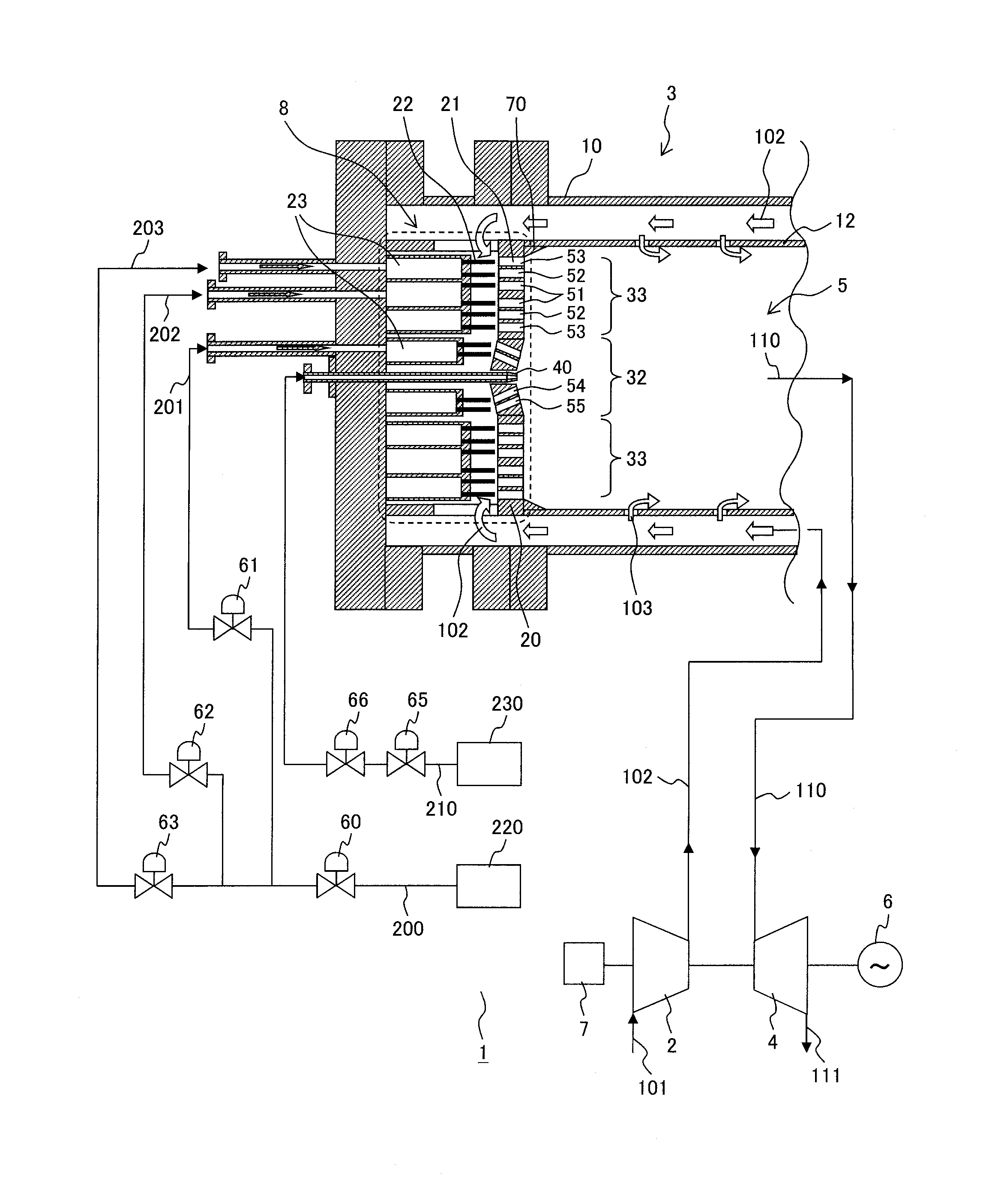
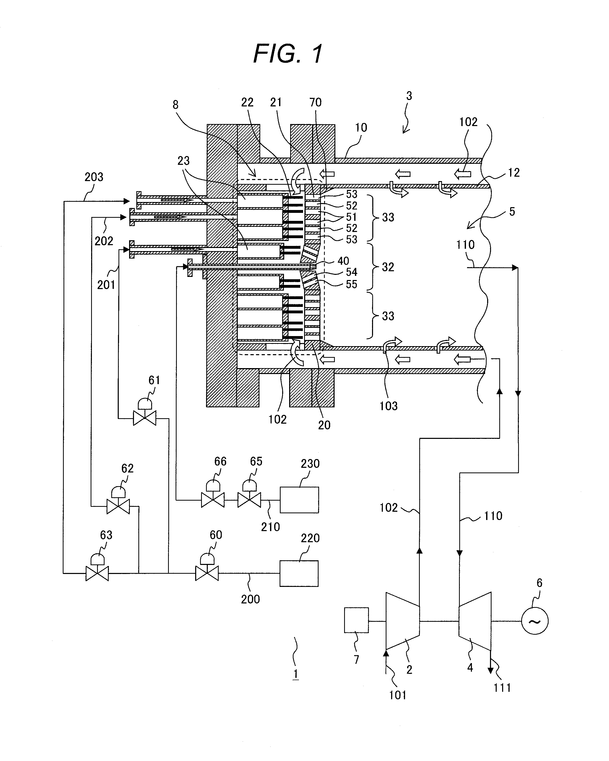
[0018]Referring to FIG. 1, a structure of the gas turbine plant will be described. FIG. 1 schematically shows the structure of the gas turbine plant which includes the gas turbine combustor (hereinafter simply referred to as “combustor”) according to the first embodiment of the present invention. The gas turbine plant 1 mainly includes an air compressor 2, a combustor 3, a gas turbine 4, and a generator 6. FIG. 1 shows part of the combustor 3 as a cross-section on a plane including the central axis of the combustor 3.

[0019]The gas turbine plant 1 is configured to generate power as below. The air compressor 2 compresses air 101 sucked from ambient air to generate compressed air 102 which is supplied to the combustor 3. The combustor 3 combusts the compressed air 102 and gas fuel 200 (201, 202, 203) to generate combustion gas 110. The gas turbine 4 is driven by the combustion gas 110 generated by the combustor 3, and discharges exhaust gas 111. The generator 6 generates power by rotat...

second embodiment

[0068]A gas turbine combustor according to a second embodiment of the present invention will be described. In the first embodiment, the combustor 3 includes the inclined component 70 on the junction between the air hole plate 20 and the combustion chamber liner 12 over the entire circumference of the combustion chamber 5. In this embodiment, the combustor 3 includes an inclined component partially formed in the combustion chamber 5 in a circumferential direction on the junction between the air hole plate 20 and the combustion chamber liner 12. The combustor 3 of this embodiment is different from that of the first embodiment only in this feature. The following description will be made with respect to the different feature.

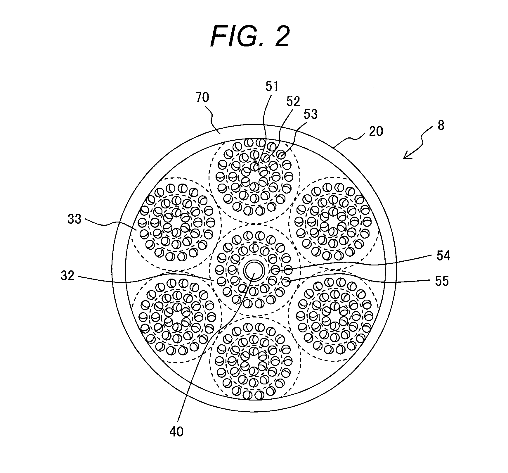
[0069]FIG. 6 is a front view of the burner 8 seen from the combustion chamber 5 likewise FIG. 2. The combustor 3 of this embodiment includes at least one inclined component 71 which is formed on at least one region of the junction between the air hole plate 20 and t...


PUM


Abstract

A gas turbine combustor of the present invention includes a cylindrical combustor liner, a cylindrical combustion chamber inside the combustor liner, and a burner that includes a plurality of fuel nozzles for injecting the gas fuel into the combustion chamber and an air hole plate with a plurality of air holes for guiding the compressed air into the combustion chamber. The air hole plate joins the combustor liner and is disposed between the fuel nozzles and the combustion chamber. The junction between the air hole plate and the combustor liner is provided with an inclined component which covers the junction and has a connecting surface connecting the air hole plate and the combustor liner.

Description

CLAIM OF PRIORITY[0001]The present application claims priority from Japanese Patent Application JP 2014-159330 filed on Aug. 5, 2014, the content of which is hereby incorporated by reference into this application.FIELD OF THE INVENTION[0002]The present invention relates to a gas turbine combustor.BACKGROUND OF THE INVENTION[0003]In view of the recent trend of power cost reduction, effective utilization of natural resources, and global warming prevention, the consideration has been made with respect to effective utilization of the byproduct gas as the fuel, for example, the coke oven gas discharged from iron works and the off-gas discharged from oil refinery. In the integrated coal gasification combined cycle power generation plant (IGCC) which generates electricity by gasifying coal of rich resources, consideration has been made for means for reducing CO2 emissions by the use of the system for capturing and storing carbon in the gas fuel (Carbon Capture and Storage or CCS).[0004]The...

Claims


Application Information

Patent Timeline
IPC IPC(8): F23R3/28F23R3/00F23R3/34
CPCF23R3/286F23R2900/00002F23R3/343F23R3/002
Inventor ASAI, TOMOHIROHAYASHI, AKINORIAKIYAMA, YASUHIRO
Owner MITSUBISHI POWER LTD
Why Eureka
Try Eureka