Double-Connection Implementation Method and Base Station

a dual connection and implementation method technology, applied in data switching networks, instruments, frequency-division multiplexes, etc., can solve the problems of increasing user terminals, network deployment environment becoming more complex, and user experience reducing, so as to ensure backward compatibility of the network, improve the performance and user experience of the user data service, and reduce the impact of control plane signaling to the network

Active Publication Date: 2016-02-11
ZTE CORP
View PDF13 Cites 20 Cited by
  • Summary
  • Abstract
  • Description
  • Claims
  • Application Information

AI Technical Summary

Benefits of technology

[0025]With the embodiment of the present invention, the connection between the network side and the terminal is no longer restricted by the transmission performance of a single link, and data shunting and distributing method can be flexibly scheduled according to the network environment or resource condition between the network side and the UE. When frequent inter-small cell handover occurs in the UE, the user data can be shunted to another connection, so it is possible to ensure the continuity of data service, and enhance performance and user experience of the user data service. Meanwhile, the service handover of the service connection between multiple flows can be implemented by changing the user plane connection, thereby reducing the impact of the control plane signaling to the network. Furthermore, the embodiment of the present invention may also be sufficient to ensure backward compatibility of the network.

Problems solved by technology

If the resource used by the link is restricted or the signal quality is relatively poor, the UE's user experience will decrease, which is a great challenge now faced by mobile operators, and although the network capacity extends year by year, it still cannot keep up with the increasing number of user terminals and the increasing user demand on data traffic.
With the increasing LPN cells, the network deployment environment becomes more complex, meanwhile it also brings some problems.
First, because the coverage of a LPN cell is much smaller compared with that of a Macro Cell, the capacity is relatively small, and some LPN cells could easily be fully occupied by users, leading to the load too high, the throughput of the user data is affected, and some other LPN cells or macro cells are at a relatively low level of load.
In order to balance the load, the network side needs to perform load balancing operation, but this process is not flexible enough, especially when the number of cells is relatively large, this phenomenon of uneven load becomes more serious because of a lack of flexibility; in addition, because the number of LPN cells is relatively large, when the user equipment, also called terminal, moves within the network, it will lead to frequent inter-cell handovers, causing frequent data service interruption or even call dropped, which causes user data throughput and user experience to decrease.
At the same time, this frequent handover results in the terminal and the network, especially the core network, receiving the impacts of a large number of signaling, which may lead to a congestion and even paralysis of system resources.
However, the abovementioned dual connectivity method currently is only at the demand and demonstration stage, and the abovementioned enhancing scheme is unable to be achieved in the current network structure and process.

Method used


Image

  • Double-Connection Implementation Method and Base Station
  • Double-Connection Implementation Method and Base Station
  • Double-Connection Implementation Method and Base Station

Examples


first application example

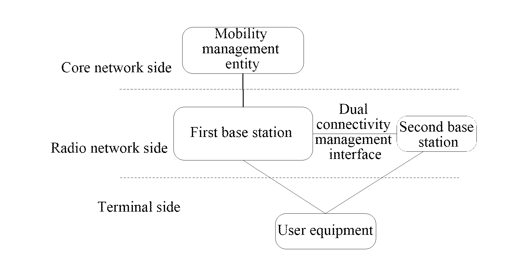
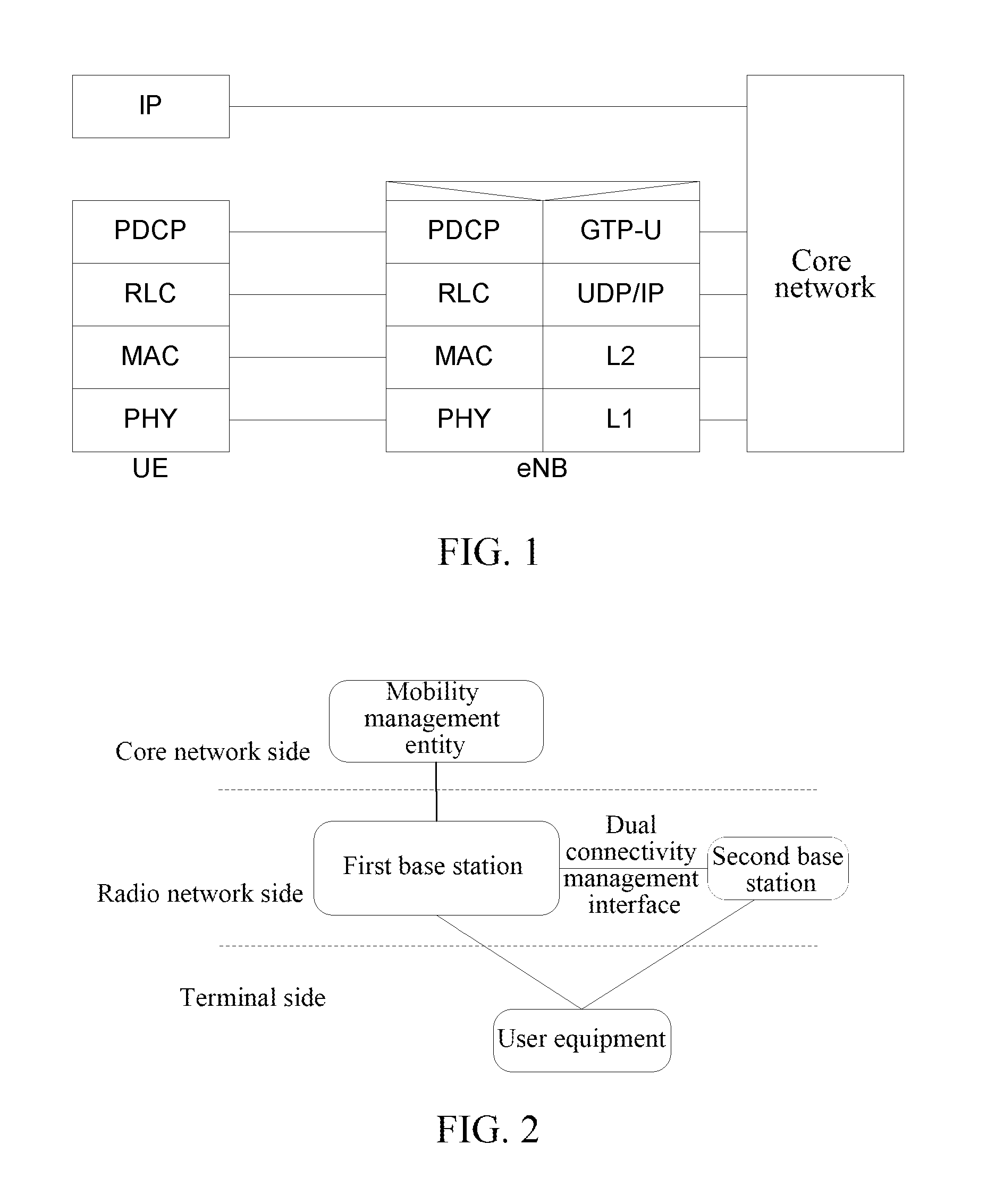
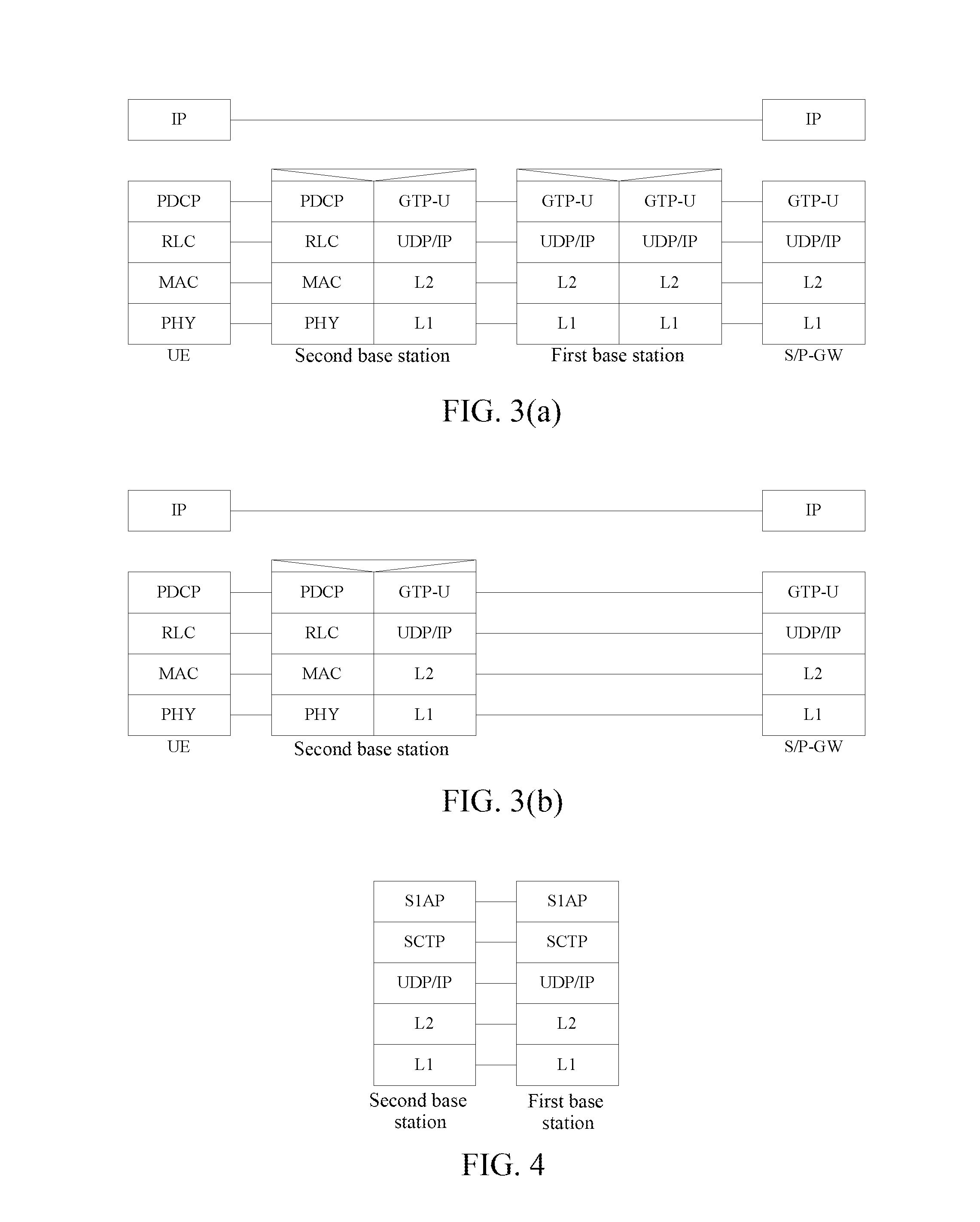
[0056]As shown in FIG. 5, there are Macro and Pico in the deployed network, wherein the UE has the service connection bearer in the first base station, that is the Macro, wherein the network-side Access Stratum and Non-Access Stratum control planes are respectively ended in the Macro and the MME, and the Macro-side user plane is ended in the core network gateway (S / P-GW). The present embodiment is described by taking the method of adding a connection of the UE in the second base station (that is, the Pico base station) as well as establishing the UE context for example, comprising the following steps:

[0057]in step 1, the Macro sends a handover request to the Pico, and the request carries information of the connection bearer which needs to be established in the Pico. Because the UE did not have a connection in the Pico previously, the context information of UE also needs to be carried in the handover request. In the step, the existing S1 interface signaling can be multiplexed for imp...

second application example

[0070]As shown in FIG. 6, there are Macro and Pico in the deployed network, and the UE has dual connectivity in the Macro and the Pico, wherein the UE only has the user plane connection in the Pico, wherein the network-side Access Stratum and Non-Access Stratum control planes are respectively ended in the Macro and the MME, and the core network user plane node is the core network gateway. The present embodiment is described by taking the method of adding a connection of the UE in the second base station, that is, the Pico base station, for example, comprising the following steps:

[0071]in step 601, the MME sends an ERAB establishment request message to the Macro, and the request message carries the ERAB information to be established.

[0072]In step 602, after receiving the message, the Macro decides to establish the newly established ERAB into the Pico according to the load information of the present base station as well as the Pico base station, or according to other established algor...

third application example

[0088]As shown in FIG. 7, there are Macro and Pico in the deployed network, and the UE has the dual connectivity in the Macro and the Pico, and it has the control plane and user plane connections in both nodes, wherein the network-side Access Stratum and Non-Access Stratum control planes are respectively ended in the Macro and the MME, and the core network user plane node is the core network gateway. The present embodiment is described by taking the method of releasing the connection of the UE in the second base station, that is, the Pico base station, for example, comprising the following steps:

[0089]in step 701, the MME sends an ERAB release command message to the Macro, wherein the message carries the ERAB information to be released.

[0090]in step 702, after receiving the abovementioned message, the Macro determines that the connection corresponding to the to-be-released ERAB exists in the Pico, thus the Macro forwards an ERAB release command message to the Pico, wherein the ERAB ...


PUM


Abstract

A method for implementing dual connectivity includes: a first base station which a user equipment accesses completing related management of a connection of the user equipment in a second base station through a dual connectivity management interface between the present base station and second base station, thereby realizing dual connectivity of the user equipment to the first base station and the second base station. The base station includes a management module, configured to: when the present base station serves as the first base station which the user equipment accesses, complete the related management of the connection of the user equipment in the second base station through the dual connectivity management interface; an acceptance module, configured to: when serving as the second base station, accept related management of the first base station for the connection of the user equipment in the present base station through the dual connectivity management interface.

Description

TECHNICAL FIELD[0001]The present document relates to a method for implementing data transmission in dual connectivity in a mobile communication system, and more particularly, to a method for implementing dual connectivity and a base station.BACKGROUND OF THE RELATED ART[0002]With constant evolution of radio communication technologies and standards, mobile packet services have been developed tremendously, and data throughput capability of a single terminal is constantly upgrading. Take the Long Term Evolution (referred to as LTE) system for example, a maximum downlink data transmission rate of 100 Mbps is supported in 20 M bandwidth, and in the subsequent LTE Advanced network, the transmission rate of data will be further increased, even up to 1 Gbps.[0003]The user plane data protocol stack of LTE is shown in FIG. 1, the downlink data received by an evolved NodeB (Evolved eNB) from the core network via the GPRS Tunneling Protocol for the user plane (referred to as GTP-U) is unpackage...

Claims


Application Information

Patent Timeline
Patent Type & Authority Applications(United States)
IPC IPC(8): H04W28/08H04W76/02
CPCH04W76/025H04W28/085H04W92/20H04W76/34H04W76/15H04W28/082H04W76/00
Inventor HE, FENG
Owner ZTE CORP
Why Eureka
Try Eureka