Surgical plan options for robotic machining

a robotic and surgical option technology, applied in the field of surgical options for navigated and/or robotic bone machining, can solve the problems of manual surgery difficulty or even impossible for surgeons, robot failure at any point during surgery, and difficulty in using conventional instruments to finish surgery with non-planar cuts at this point, etc., to achieve the effect of improving accuracy, reproducibility and speed

Inactive Publication Date: 2016-02-18
STRYKER CORP
View PDF2 Cites 28 Cited by
  • Summary
  • Abstract
  • Description
  • Claims
  • Application Information

AI Technical Summary

Benefits of technology

[0016]In yet another embodiment of the invention, a method of performing surgery on a bone includes providing a robotically controlled bone preparation system to make bone resections. The method may also include operating the robotically controlled bone preparation system to machine the bone to have features corresponding to features of a surgical instrument, wherein the robotic machining has at least one of increased accuracy, reproducibility, and speed compared to manual resections. The method may further include manually completing the surgery on the bone without further use of the robotically controlled bone preparation system, including the step of manually coupling the surgical instrument to the bone.

Problems solved by technology

This plan may involve, for example, precise non-planar cuts that would be difficult or even impossible for a surgeon to make manually.
While such a robotic plan may provide for potential advantages over traditional manual plans using conventional tools and planar cuts, there is always a possibility that the robot may fail at any point during surgery.
If the robot fails mid-surgery, for example, the surgeon may need to use conventional instrumentation to complete the particular procedure.
However, this may be difficult as bone has already been removed by the robot, generally with non-planar cuts.
While conventional instrumentation is generally used in conjunction with planar cuts and with pre-drilled reference points, making the use of conventional instruments to finish the surgery with non-planar cuts at this point would be difficult.

Method used


Image

  • Surgical plan options for robotic machining
  • Surgical plan options for robotic machining
  • Surgical plan options for robotic machining

Examples


Embodiment Construction

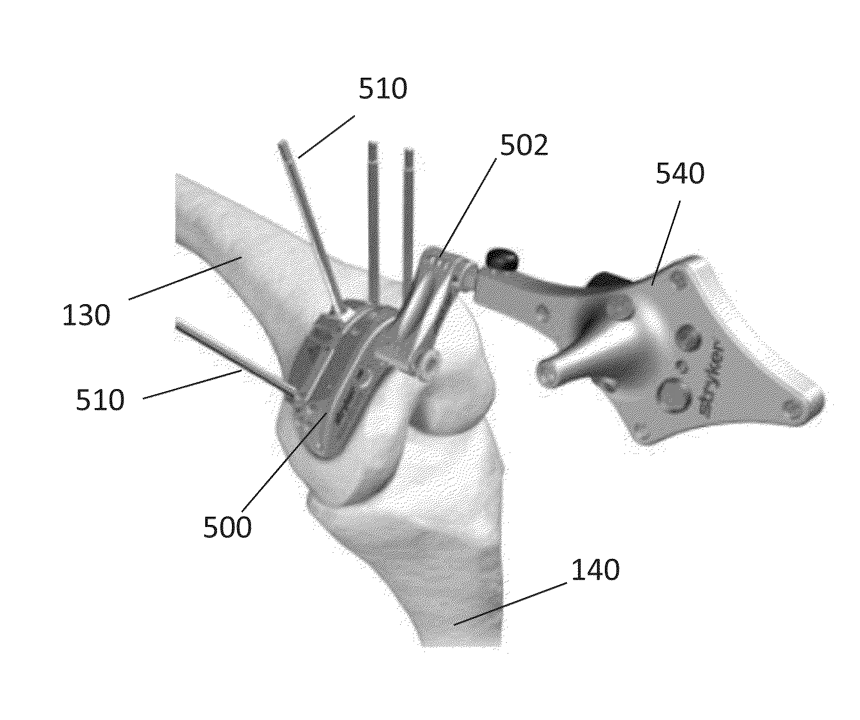
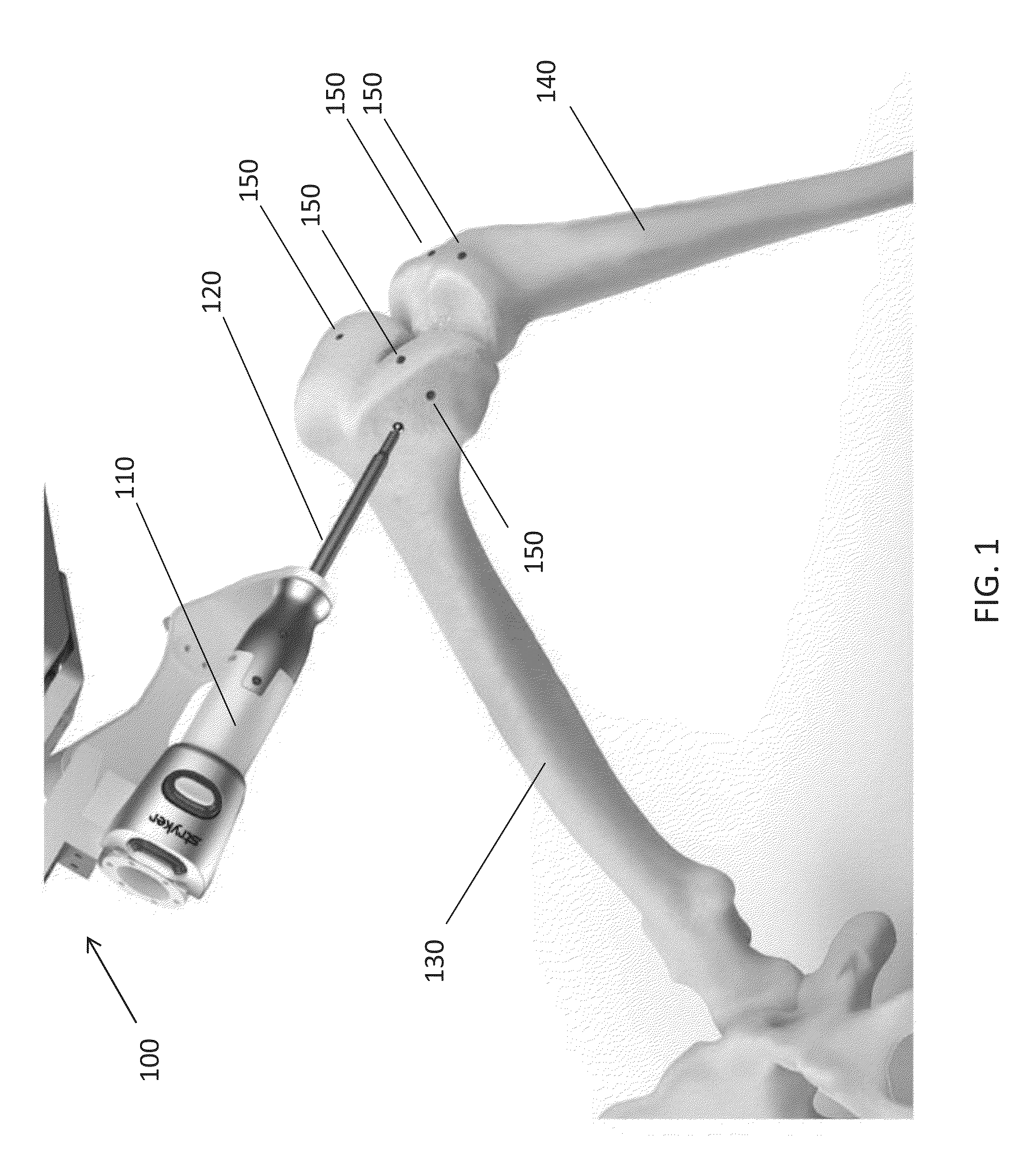
[0045]As used herein, the term “distal” means more distant from the heart and the term “proximal” means closer to the heart. The term “inferior” means toward the feet and the term “superior” means towards the head. The term “anterior” means towards the front part of the body or the face and the term “posterior” means towards the back of the body. The term “medial” means toward the midline of the body and the term “lateral” means away from the midline of the body. Terms including “debulking,”“resecting,”“machining,”“finishing,” and “bone preparation,” are used interchangeably herein, and all generally refer to the removal and / or reshaping of bone.

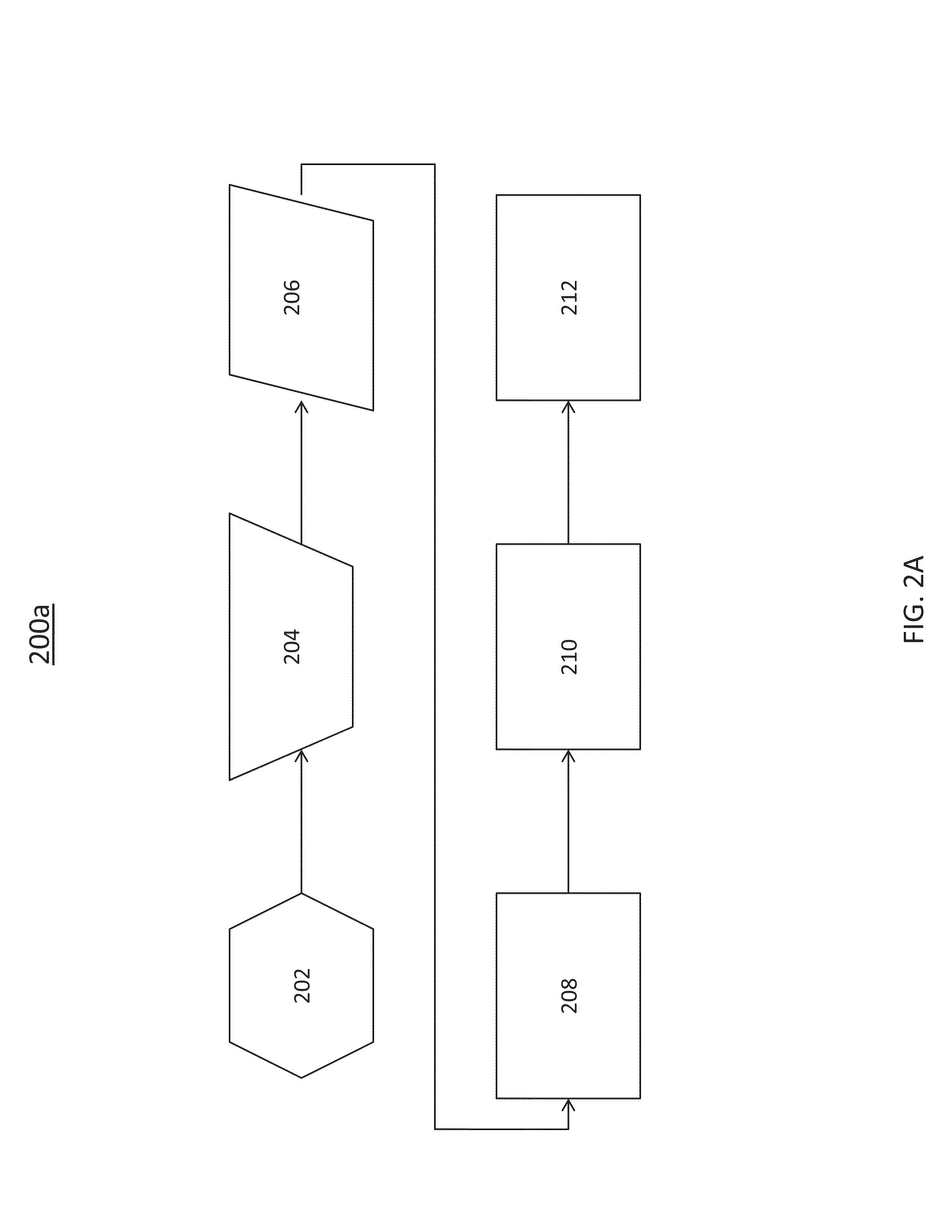
[0046]In the figures, with particular reference to the flow charts contained therein, a step enclosed in a hexagon indicates a tool-change step, a step enclosed in a trapezoid indicates a knee-positioning step, a step in a parallelogram indicates a registration step, a step enclosed in a diamond may indicate a step which branches into multip...


PUM


Abstract

A method of performing surgery on a bone includes providing a robotically controlled bone preparation system and creating at least one hole in the bone with the robotically controlled bone preparation system prior to machining the bone. The bone hole aligns with a hole or a post in a guide for a manual cutting tool. If the robot fails during surgery, or if the surgeon does not wish to complete the procedure with the robot, the guide is attached to the bone after aligning the guide hole with the bone hole. The surgery is completed manually after the guide is attached to the bone, and the robot is not used after the guide is attached to the bone.

Description

FIELD OF THE INVENTION[0001]The present invention relates to surgical options for navigated and / or robotic bone machining and in particular relates to having the option of completing joint arthroplasty procedures with conventional instruments following the use of navigated and / or robot based applications.BACKGROUND OF THE INVENTION[0002]In a traditional joint arthroplasty procedure, such as a total knee arthroplasty (“TKA”) surgery, diseased bone and / or cartilage of a patient is generally removed and replaced with a prosthetic implant. A surgeon may resect the bone using a hand-held oscillating saw blade which results in a series of planar bone surfaces. Additionally, the surgeon may use a drill, broach or tamp instrument to make cylindrical holes into the bone in order to accommodate fixation features on the implant. The planar bone surfaces and cylindrical bone holes, for example, are generally oriented to interface with flat surfaces and pegs or keels of a prosthetic implant.[000...

Claims


Application Information

Patent Timeline
Patent Type & Authority Applications(United States)
IPC IPC(8): A61B17/16A61B17/17A61B17/32
CPCA61B19/2203A61B17/1675A61B2017/320052A61B17/32A61B2019/2207A61B17/1764A61B17/155A61B17/157A61B34/30A61B90/11
Inventor KEPPLER, LOUPRABAHARAN, SATHIYAHAMPP, EMILYAXELSON, JR., STUART L.FOSSEZ, JOHN R.
Owner STRYKER CORP
Why Eureka
Try Eureka