Variable hip resurfacing femoral implant

a femoral implant and variable technology, applied in the field of hip resurfacing arthroplasty, can solve the problems of pain and disability, lack of modularity through threaded attachments, and affect a large segment of the population, so as to increase the strength of the implant, and supplement the effect of the construct strength

Inactive Publication Date: 2016-02-18
REVORTHO
View PDF2 Cites 7 Cited by
  • Summary
  • Abstract
  • Description
  • Claims
  • Application Information

AI Technical Summary

Benefits of technology

[0009]The variable hip resurfacing system according to an example embodiment of the present invention has threading at the base of its stem for modular attachments. This allows for the addition of a central screw, which can be used in combination with a femoral plate to significantly increase construct strength, when required.
[0010]An additional advantage of the variable hip resurfacing implant according to an example embodiment of the present invention is additional threaded holes along the undersurface of the upper cap portion. These additional threaded holes allow for multiple scalable fixation options, which can be used to further supplement construct strength in the setting of localized bone deficiencies. If localized bone deficiencies are e

Problems solved by technology

Degenerative conditions of the hip joint results in pain and disability and affects a large segment of the population.
A limitation of the Amstutz and BHR systems is a lack of modularity through threaded attachments for supplementing fixation of the implant to the underlying bone.
No additional fixation options are available in instances where poor bone quality is encountered.
Local areas of bone deficiency can often be encountered in patie

Method used


Image

  • Variable hip resurfacing femoral implant
  • Variable hip resurfacing femoral implant
  • Variable hip resurfacing femoral implant

Examples


Embodiment Construction

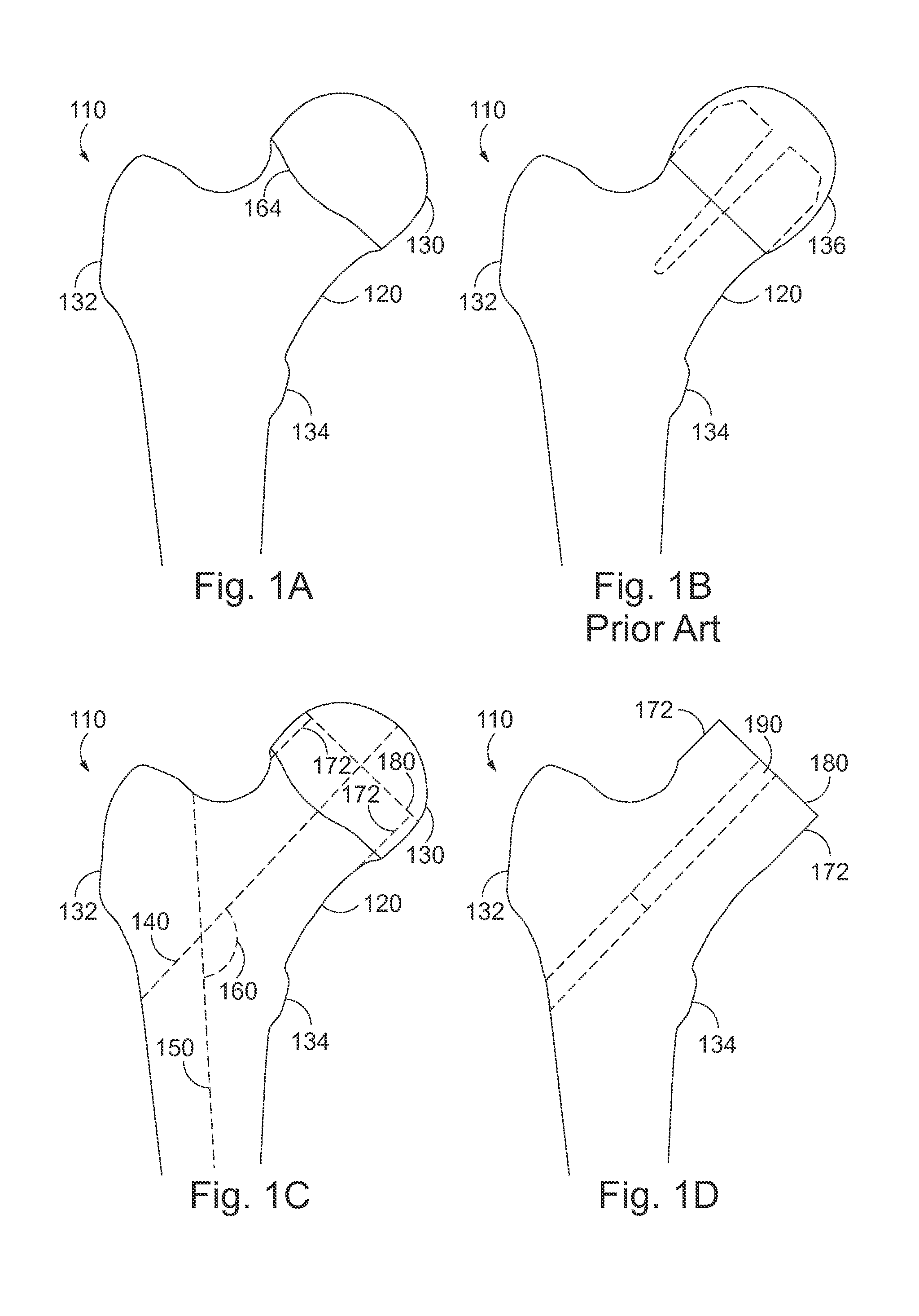
[0044]FIG. 1A is a front view from anterior of a human proximal femur 110 including femoral neck 120, femoral head 130, greater trochanter 132, lesser trochanter 134 and cartilage border, articular rim 164. FIG. 1B is a front view illustrating a proximal femur 110 following bone cuts and implantation of a hip resurfacing femoral implant 136, according to previous devices such as the Birmingham Hip Resurfacing implant. The dashed line in FIG. 1B illustrates the required bone cuts following cylindrical reaming and osteotomies, for hip resurfacing femoral implants according to previous devices. Such a hip resurfacing femoral implant, as illustrated, has a solid stem without internal threading. Bone preparations for implantation of this hip resurfacing implant include cylindrical reaming of the femoral head 130. This implant lacks threaded holes along its undersurface to accommodate optional threaded modular attachments, thus limiting implantation options.

[0045]FIG. 1C is a front view o...


PUM


Abstract

A variable hip resurfacing implant which allows for varying configuration options to account for characteristics of underlying degenerative hip joint disease and for both un-cemented and cemented application. The variable hip resurfacing implant generally includes a femoral head portion, bearing surface, outer rim, inner planar surface, central stem, and a central stem threaded hole.

Description

CROSS-REFERENCE TO RELATED APPLICATIONS[0001]The present application claims the benefit of U.S. Provisional Patent Application Ser. No. 62 / 038,763, filed Aug. 18, 2014, the entire contents of which is incorporated herein by reference thereto.FIELD OF THE INVENTION[0002]The present invention relates to hip resurfacing arthroplasty.BACKGROUND INFORMATION[0003]Degenerative conditions of the hip joint results in pain and disability and affects a large segment of the population. Conditions which can lead to onset of hip disease include cartilage injury, osteoarthritis, avascular necrosis, and other hip joint pathologies such as mechanical abnormalities. Multiple operative treatment modalities and implants have been promoted over time with the aim of relieving pain and restoration of improved hip joint mechanics. Initial attempts at surgical treatment completely removed and replaced the femoral head with a metallic implant, which was connected to a load-bearing femoral stem. This represen...

Claims


Application Information

Patent Timeline
IPC IPC(8): A61F2/36A61B17/16
CPCA61F2/3609A61F2002/365A61B17/1668A61F2/30749A61F2/3603A61F2002/30299A61F2002/30433A61F2002/30774
Inventor KLINGER, CRAIG ERICTORO ARBELAEZ, JOSE BERNARDO
Owner REVORTHO
Why Eureka
Try Eureka