Magnetic cycloid gear

a magnetic gear and cycloid technology, applied in the direction of machines/engines, rotary/oscillating piston pump components, borehole/well accessories, etc., can solve the problems of requiring periodic lubrication and maintenance, mechanical components of gearboxes are subject to wear and fatigue, and produce relatively large acoustic noise and vibration

Inactive Publication Date: 2016-02-18
NAT OILWELL VARCO LP
View PDF2 Cites 11 Cited by
  • Summary
  • Abstract
  • Description
  • Claims
  • Application Information

AI Technical Summary

Benefits of technology

[0014]It is to be understood that both the foregoing general description and the following detailed description are exemplary and explanatory only and are not restrictive of the invention, as claimed. It should be understood that the invention, in its broadest sense, could be practiced without having one or more features of these exemplary aspects and embodiments.

Problems solved by technology

Such mechanical gearboxes, however, may produce relatively large acoustic noise and vibration.
Also, the mechanical components of gearboxes are subject to wear and fatigue (e.g., tooth failure), and require periodic lubrication and maintenance.
Moreover, mechanical gear arrangements can have inefficiencies as a result of contact friction losses.
The flexible spline structures of mechanical harmonic gears are a relatively weak structural component that limits the output torque of such gears, thus providing relatively low output torques.

Method used


Image

  • Magnetic cycloid gear
  • Magnetic cycloid gear
  • Magnetic cycloid gear

Examples


Embodiment Construction

[0037]Reference will now be made in detail to various exemplary embodiments of the present disclosure, examples of which are illustrated in the accompanying drawings. Wherever possible, the same reference numbers will be used throughout the drawings to refer to the same or like parts.

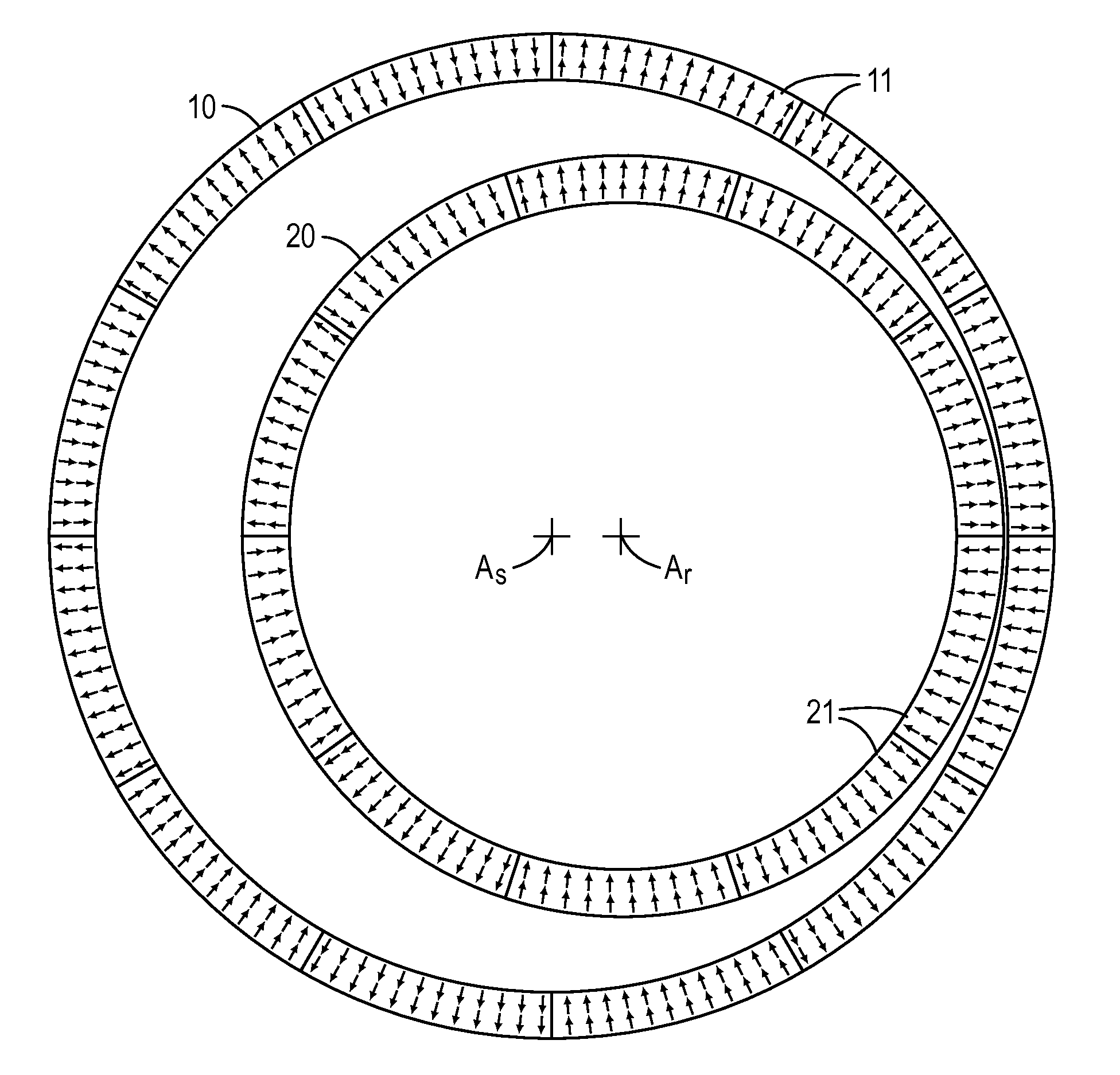
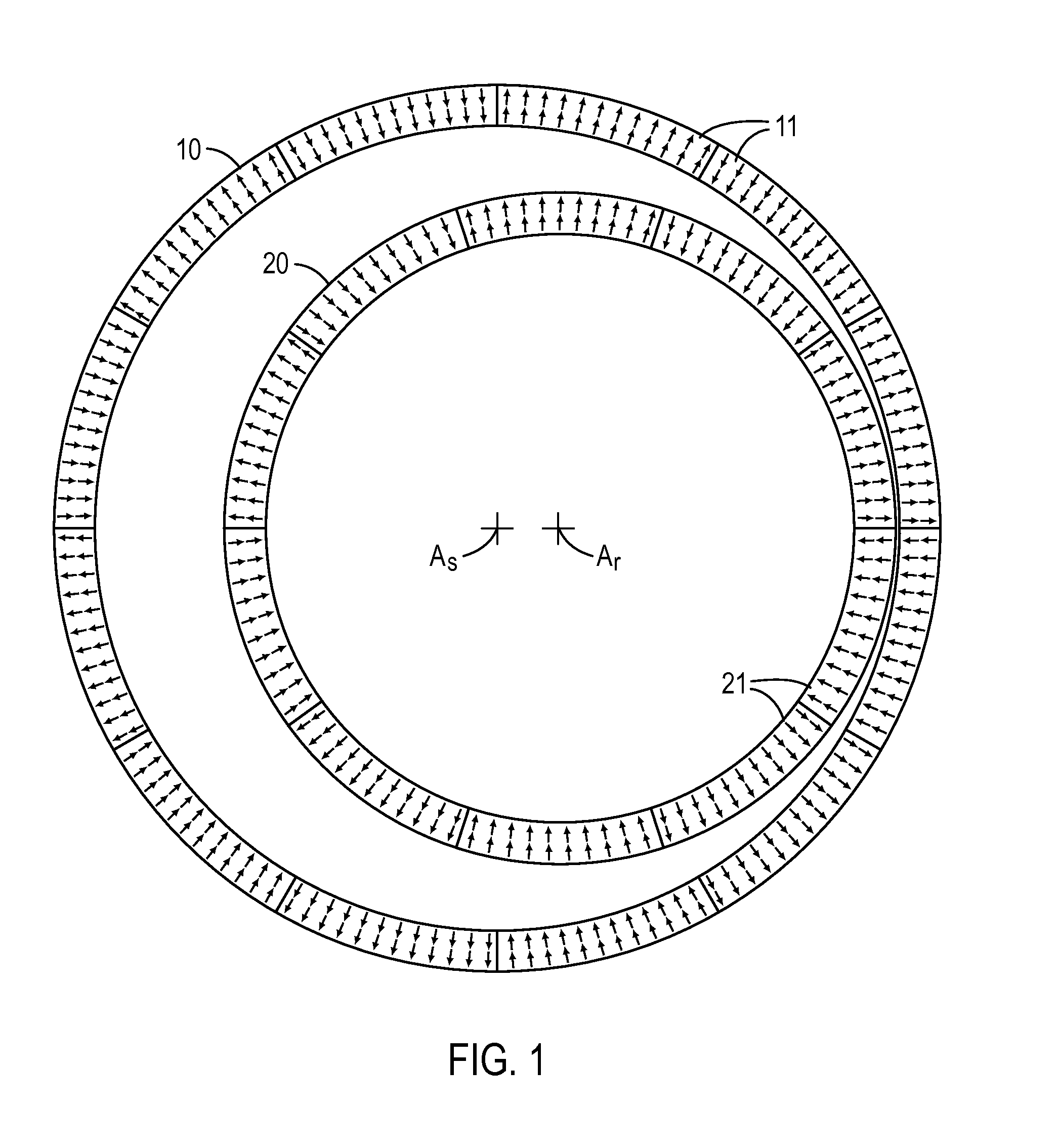
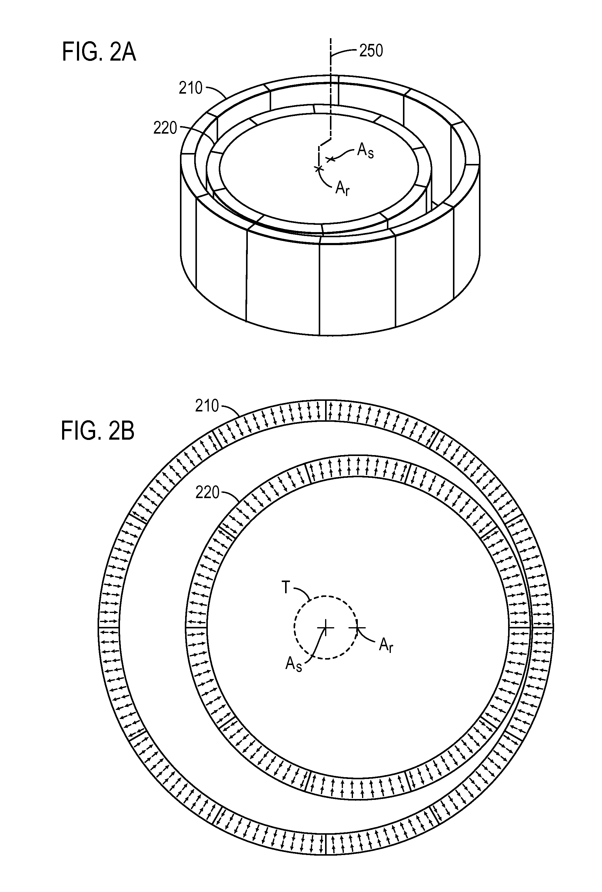
[0038]In accordance with various exemplary embodiments, magnetic cycloid gear arrangements can provide improved performance (e.g., gear ratios and output torque densities) with less magnet volume than various other magnetic gear configurations. For example, various exemplary embodiments of magnetic cycloid gears described herein may have gear ratios that are on the order of or greater than 30:1, for example about 31:1. In various exemplary embodiments, the magnetic cycloid gears can be sized to achieve a torque output sufficient for driving rotary equipment, such as a top drive, in an oil drilling rig. For example, the torque output may range from about 25,000 ft-lbs to about 29,000 ft-lbs. In an exempl...


PUM


Abstract

A magnetic cycloid gear includes an outer gear member comprising a first plurality of magnets that provide a first number of magnetic pole pairs, wherein the outer gear member has an outer gear member axis, and an inner gear member comprising a second plurality of magnets that provide a second number of magnetic pole pairs, wherein the inner gear member has an axis that is offset from the outer gear member axis and wherein the second number of magnets differs from the first number of magnets. The gear further includes a drive mechanism operatively coupled to rotate the inner gear member as it revolves in an eccentric manner relative to the outer gear member axis, and a constraint mechanism coupled to the inner gear member to prevent it from rotating bout its own axis as it revolves. The outer gear member rotates in response to the inner gear member revolving.

Description

CROSS-REFERENCE TO RELATED APPLICATIONS[0001]This application claims priority to U.S. Provisional Patent Application No. 61 / 783,636, filed Mar. 14, 2013 and entitled “Magnetic Cycloid Gears, and Related Systems and Methods,” which is incorporated by reference herein in its entirety.TECHNICAL FIELD[0002]The present disclosure relates generally to radial cycloid magnetic gears, and related systems and methods, including for example, for use in various rotary driven industrial equipment, such as, for example, top drives, drawworks, and / or mud pumps of oil rigs.INTRODUCTION[0003]The section headings used herein are for organizational purposes only and are not to be construed as limiting the subject matter described in any way.[0004]Gearboxes and gear arrangements are utilized in a wide range of applications in order to provide speed and torque conversions from a rotating power source to another device. Traditionally, gearboxes have been formed from gear rings, or wheels, each being size...

Claims


Application Information

Patent Timeline
Patent Type & Authority Applications(United States)
IPC IPC(8): H02K49/10E21B3/02E21B19/02E21B21/01
CPCH02K49/106E21B3/02H02K49/102E21B21/01E21B19/02H02K5/132H02K7/11H02K7/14F04C15/0069F04C13/002E21B3/022
Inventor DAVEY, KENT, R.
Owner NAT OILWELL VARCO LP
Why Eureka
Try Eureka