High effectiveness low pressure drop heat exchanger

a heat exchanger and low pressure drop technology, applied in the direction of machines/engines, laminated elements, lighting and heating apparatus, etc., can solve the problems of low efficiency of heat exchangers, difficult trade-offs, and the pressure ratio of recuperators that is higher, so as to achieve low weight, low pressure drop, and high efficiency

Active Publication Date: 2016-02-25
MOHAWK INNOVATIVE TECH
View PDF13 Cites 19 Cited by
  • Summary
  • Abstract
  • Description
  • Claims
  • Application Information

AI Technical Summary

Benefits of technology

[0038]It is accordingly an object of the present invention to maximize heat transfer while minimizing pressure drop in a heat exchanger.
[0041]In order to achieve the above objects, in accordance with the present invention, a heat exchanger is provided wherein each fluid passage is bounded by at least three walls (triangular in cross-section) with each wall serving as a wall for an adjacent passage for heat transfer across the walls to adjacent passages and providing for both co-flow (as used herein and in the claims, defined as the type of flow wherein both fluids on opposite sides of a wall flow in the same direction) and counter-flow (as used herein and in the claims, defined as the type of flow wherein the fluids on opposite sides of a wall flow in opposite directions) which allows for design adjustment to achieve a maximized heat transfer at a minimized pressure drop, as suitable or optimum for the specific application.
[0042]Such a heat exchanger having co-flow as well as counter-flow of its fluids, with perhaps also some cross-flow heat transfer (wherein the flow of one fluid may be said to be generally normal to the flow of an other fluid, which may be brief transition flow as the fluid changes direction to flow in the opposite direction), is referred to herein and in the claims as a “mixed mode” heat exchanger. Such a mixed mode heat exchanger is arranged, as discussed herein, to provide high effectiveness (defined as the ratio of actual heat exchanged to the theoretical maximum for given conditions) and a low pressure drop on the working flow streams. In general, its high effectiveness and low pressure penalty characteristics are provided to make it suitable for application to a pressure-drop sensitive device that may benefit from exhaust heat recuperation, such as, but not limited to, Ericsson Cycle engines, drying fluid Organic Rankine Cycle engines, or preheated cathode-air fuel cells. In particular, in a radial configuration, it is considered to be ideally suitable for use as a Brayton Cycle gas turbine engine recuperator.
[0043]A preferred heat exchanger is provided with two or more overlapping helical flow paths, over which two or more working flows are distributed. For an example of a three or more flow path heat exchanger, such a heat exchanger may be provided for the purpose of equalizing the temperatures of three or more fluid streams. For such a distribution of two or more flows, at any location, the passage walls surrounding a given stream of each working flow are in contact with streams of a different working flow, thereby to establish an alternating patchwork pattern such as what might be called a chessboard pattern of hot / cool gas flow, thereby to maximize heat transfer between working flows while minimizing pressure drop. The flow paths or trajectories are defined by parallel or radially oriented stacks of thin-walled circuits of rectangular, triangular, or other polygonal cross-section.
[0044]For a preferred heat exchanger for a gas turbine engine, flows from a compressor discharge and turbine exhaust flow into the heat exchanger, where they are divided over a multiplicity of serpentine passages. The serpentine passages are arranged such that as an individual stream flows through the unit, it is forced to follow a helical flow path of relatively small axial pitch, first moving radially outwardly through one passage or duct, being made to turn in the axial direction, then radially inwardly through another passage or duct, and forced to turn axially again, then again moving radially outwardly, with this pattern repeating multiple times along the length of the heat exchanger. By overlapping the helical flow paths, the passages carrying one working flow are staggered in the aforementioned chess-board pattern with respect to those passages carrying the other flow or which may be characterized as a spiral pattern, i.e., like a screw thread. In this manner, the walls of each passage or duct represent boundaries separating streams of the different working fluids, allowing for the maximization of heat transfer while minimizing pressure drop.

Problems solved by technology

In practical terms, a heat exchanger cannot achieve 100% effectiveness or zero pressure drop impact on the engine.
These two conditions have typically involved competing design requirements, which result in difficult tradeoffs that must be balanced according to the specific needs of the target application.
If the adiabatic efficiency of the turbine and compressor are high enough, which however is normally difficult to achieve, the pressure ratio where a recuperator could be used would be higher.
They were not able to find commercially a recuperator providing the desired high efficiency but of a suitably light weight so that the gas turbine engine could still be light enough so that the recuperated gas turbine could be portable by a foot soldier.
High heat transfer effectiveness requires long flow residence times, large heat exchange surface areas, and potentially heat exchange-increasing features, like surface rugosity or turbulence enhancers, all of which result in high pressure drop.
The incorporation of these features may result in relatively voluminous passage walls and hardware, over which thermal gradients form that ultimately translate into parasitic heat losses to ambient.
Additionally, the pressure difference between working fluids may produce net forces on the heat exchange surfaces that may require fabrication with thicker passage walls.
Ultimately, practical considerations typically result in compromises that sacrifice effectiveness for lower pressure drop, or vice-versa, or which sacrifice robustness to pressure loading.
For example, it describes the use of thin plate counter-flow heat exchangers in U.S. Pat. No. 5,983,992, or an annular recuperator composed of side-by-side annular plates described in U.S. Pat. No. 5,388,398, both of which result in geometries that make the recuperators difficult to manufacture, and exhibit insufficient robustness to leaks or differential pressure loading.
The annular flow concentric tube recuperator presented in the afore-mentioned U.S. Pat. No. 6,390,185 exhibits some drawbacks, like operation in a laminar regime (at high flow rates, maintaining laminarity undesirably requires a large number of small cross-section passages), possible issues with flow mal-distribution, and difficult incorporation as an integral component of a gas turbine housing or combustor.
This heat exchanger is geometrically complex and costly to fabricate.
Such a connecting piece arrangement provides for all flows of a fluid in the same direction from one end to the other through the heat exchanger, which undesirably prevents the ability to provide both counter-flow and co-flow.
None of the above references allows ease of design adjustment of the flow passages to achieve a balance between a maximized heat transfer at a minimized pressure drop, as suitable or optimum for a specific application.
If it can be done, it may be difficult to scale down to the size of a portable meso-scale turbine which maintains a low pressure burden.

Method used


Image

  • High effectiveness low pressure drop heat exchanger
  • High effectiveness low pressure drop heat exchanger
  • High effectiveness low pressure drop heat exchanger

Examples


Embodiment Construction

)

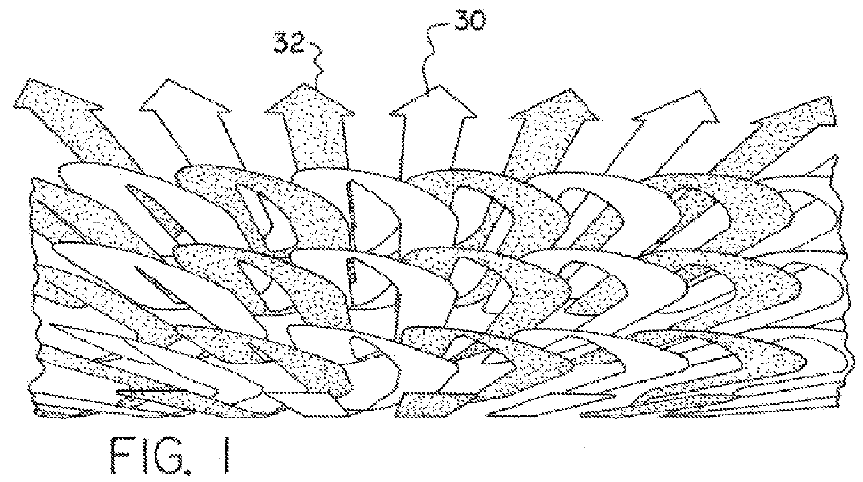
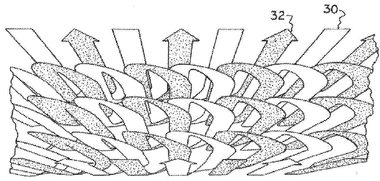
[0064]Conceptually, and independent of any particular hardware incarnation to attain them, the flow paths are illustrated by the overlapping quasi-helical arrows 30 and 32 in FIGS. 1 and 2. The arrows 30 and 32, shown shaded in lighter and darker tones respectively, represent two different working flows, say hot and cold respectively, though the present invention should not be considered as limited to two flows, as more than two working flows may be accommodated.

[0065]FIG. 1 illustrates the relationship between the overlapping paths 30 and 32 as if the fluids enter a heat exchange device from the same side or terminus, following quasi-helical or generally helical (which herein may be called “helical”) trajectories that may be said to fold over each other, thereby establishing, as can be seen in FIG. 1, overlapping regions of flows of fluids which have different temperatures. This allows the flow paths 30 and 32 to be arranged so that counter-flow heat transfer may occur across boun...


PUM


Abstract

A heat exchanger in the form of a honeycomb with a plurality of rectangular or otherwise polygon in cross-section passages which share common walls with adjacent passages. Two or more flow paths each comprises a plurality of serially connected passages. Each flow path passes through the heat exchanger in a helical pathway, thus through one passage in a first vertical stack of passages, then through a lower passage in an adjacent second vertical stack of passages, then through a lower passage in the first vertical stack, then through a lower passage in the second vertical stack and in this helical manner to the outlet from the heat exchanger. Thus, the flow path comprises alternate passages in each vertical stack, and another flow path comprises the alternate passages in at least one of the vertical stacks not taken up by the first flow path, whereby the flow paths at least partially overlap each other thereby providing both counter-flow and co-flow.

Description

[0001]The priority of U.S. provisional application 62 / 040,559, filed Aug. 22, 2014, the disclosure of which is incorporated herein by reference, is hereby claimed.[0002]The present invention is generally related to the field of heat exchangers such as, for example, compact high temperature gas-to-gas heat exchangers such as, but not limited to, recuperators for Ericsson Cycle engines, drying fluid Organic Rankine Cycle engines, preheated cathode-air fuel cells, and Brayton Cycle gas turbine engines. While the present invention is discussed herein primarily in the context of Brayton Cycle gas turbine engines, it may be applied to a general application heat exchanger, and the present application should not be read as limiting the scope of application of the invention or its principle of operation.BACKGROUND[0003]A Brayton Cycle gas turbine engine extracts energy from a flow of gas to produce shaft power, thrust, compressed air, or a combination of these, and generally comprises a turb...

Claims


Application Information

Patent Timeline
Patent Type & Authority Applications(United States)
IPC IPC(8): F28D7/08
CPCF28D7/087F28F7/02F28F9/26F28D9/0018F28D21/001F28D2021/0026F28D7/0008F02C7/08F28D7/085
Inventor CORDOVA, JOSE LUISHESHMAT, HOOSHANG
Owner MOHAWK INNOVATIVE TECH
Why Eureka
Try Eureka