Eureka AIR delivers breakthrough ideas for toughest innovation challenges, trusted by R&D personnel around the world.

Control device for an internal combustion engine

Inactive Publication Date: 2016-03-03
MITSUBISHI ELECTRIC CORP
View PDF10 Cites 5 Cited by
  • Summary
  • Abstract
  • Description
  • Claims
  • Application Information

AI Technical Summary

Benefits of technology

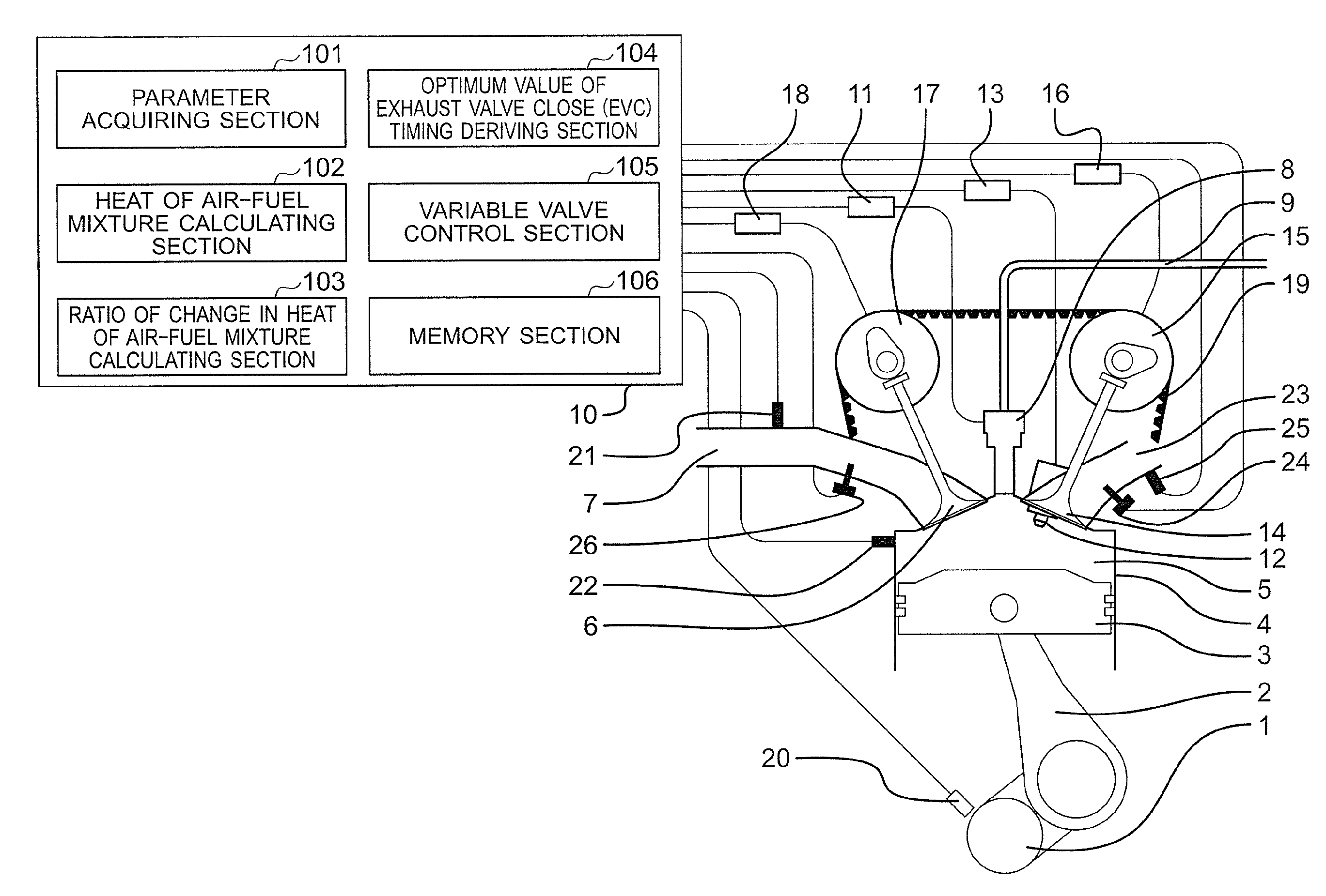
The present invention provides a control device for an internal combustion engine that can prevent knocking and misfire caused by changes in operating state in previous cycles. This is achieved by controlling the valve timing of the exhaust valve to optimize the air-fuel mixture and prevent excessive heating of the air-fuel mixture. This technology ensures that the engine runs smoothly and prevents damage caused by pre-ignition and misfire.

Problems solved by technology

On the other hand, the thermal efficiency is low in an operating region in which the internal combustion engine load is relatively low.
Therefore, the amount of intake-air cannot be greatly increased.
Thus, a great effect of improving the thermal efficiency is not obtained.
However, means for heating the intake air is required.
Thus, a device configuration becomes complex.
In some cases, however, the temperature of the air-fuel mixture at the time of compression changes to cause pre-ignition or misfire depending on a difference of the temperature of the combustion gas and the temperature and amount of the intake air.
However, the related art has the following problems.
Thus, there is a problem in that knocking due to pre-ignition occurs.
Thus, there is a problem in that misfire occurs.

Method used


Image

  • Control device for an internal combustion engine
  • Control device for an internal combustion engine
  • Control device for an internal combustion engine

Examples


first embodiment

[0025]First, in order to clarify technical features of the present invention, a problem of an internal combustion engine with the application of the related art described in Japanese Patent Application Laid-open No. 2009-150288, which the inventors of the present invention newly focus on, is described referring to FIG. 4. FIG. 4 is an explanatory diagram showing an example of a database for setting a valve-closing timing of an exhaust valve with the application of the related art.

[0026]In this case, an internal EGR gas is a part of a combustion gas derived in a previous cycle, which is left in a combustion chamber. Further, as a result of mixture of the internal EGR gas and air and a fuel that are newly taken and supplied in a current cycle, an air-fuel mixture is formed. Combustion of the thus formed air-fuel mixture is significantly affected by a temperature and a density of the air-fuel mixture.

[0027]The internal EGR gas temperature is high relative to an air temperature and a co...

second embodiment

[0099]In the first embodiment described above, the case where the optimum value of exhaust valve close (EVC) timing for allowing the absolute value of the ratio of change in heat of air-fuel mixture to become equal to or smaller than the reference value is derived is described. On the other hand, in a second embodiment of the present invention, the following configuration is described. Specifically, the heat of air-fuel mixture in the previous cycle is adjusted so as to be increased or decreased in the current cycle in accordance with a magnitude relationship between the combustion load in the previous cycle and that in the current cycle. In addition, the optimum value of exhaust valve close (EVC) timing for allowing the absolute value of the ratio of change in heat of air-fuel mixture to become equal to or smaller than the reference value is derived.

[0100]Here, as compared with a case of a steady combustion with a small combustion load, the temperature of the internal EGR gas remai...


PUM


Abstract

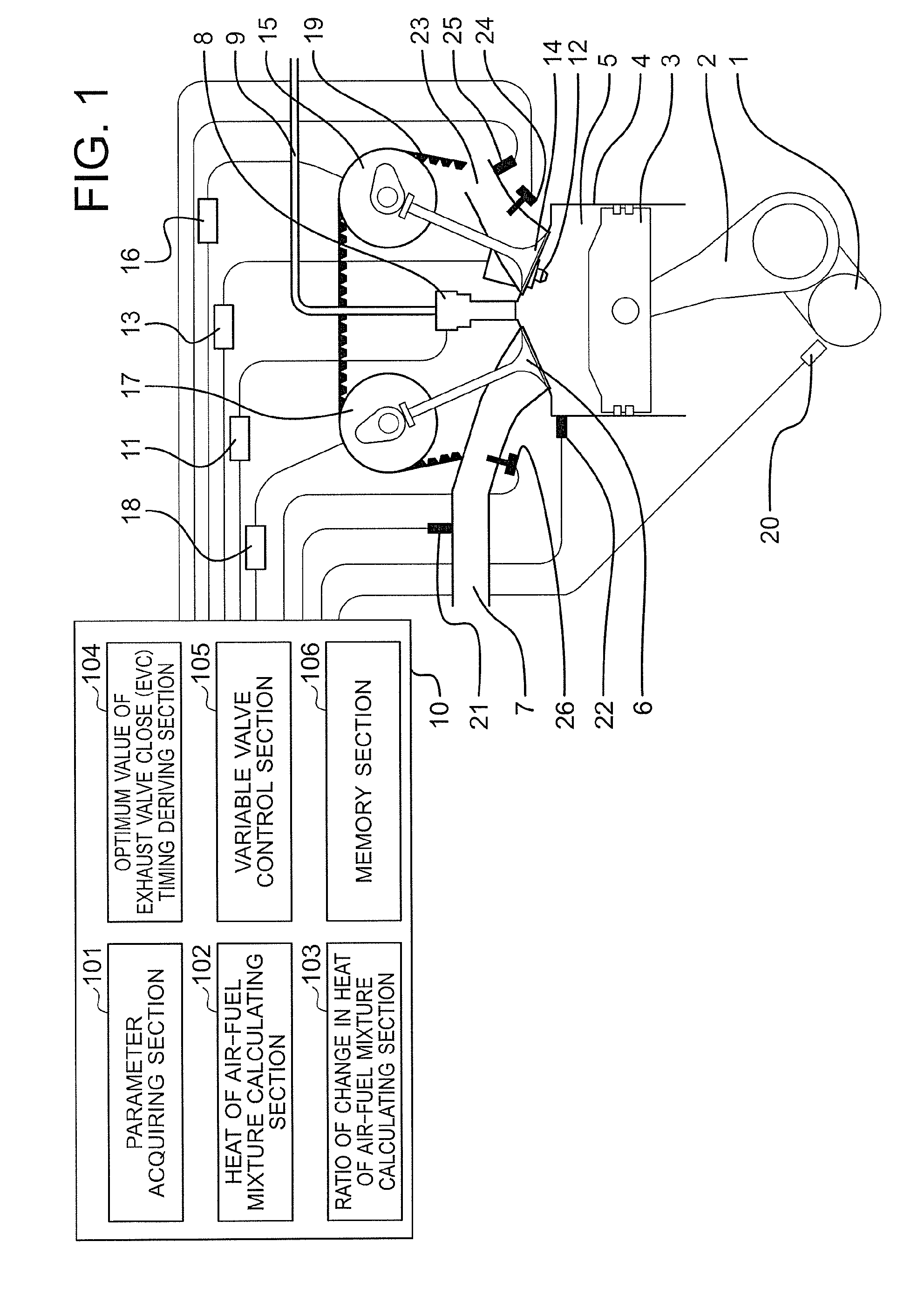
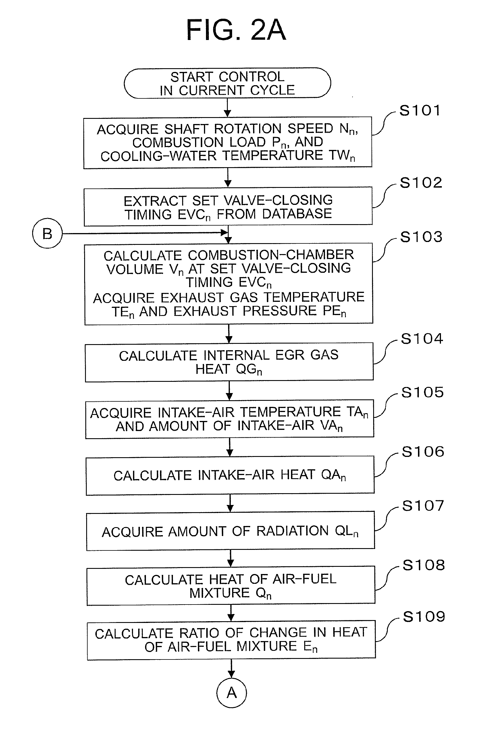
Provided is a control device for an internal combustion engine, which is capable of suppressing occurrence of knocking due to pre-ignition and occurrence of misfire even when an operating state in a previous cycle changes in a subsequent cycle. When a ratio of change in heat of air-fuel mixture, which is an index indicating how a heat of air-fuel mixture in the previous cycle changes in the subsequent cycle, does not fall within an allowable range, a variable valve control mechanism capable of changing a valve-closing timing of an exhaust valve for adjusting an internal EGR gas amount is controlled by using an optimum value of exhaust valve close (EVC) timing derived by correcting a set valve-closing timing of the exhaust valve so that the ratio of change in heat of air-fuel mixture falls within the allowable range.

Description

BACKGROUND OF THE INVENTION[0001]1. Field of the Invention[0002]The present invention relates to a control device for an internal combustion engine, for controlling the amount of internal EGR gas that is a burnt gas remaining in a cylinder.[0003]2. Description of the Related Art[0004]In a related-art spark-ignition internal combustion engine using gasoline as a fuel, a thermal efficiency is high in an operating region in which an internal combustion engine load is middle to high. On the other hand, the thermal efficiency is low in an operating region in which the internal combustion engine load is relatively low. The operating region with the relatively low internal combustion engine load is frequently used for automobiles. As a factor of reduction in thermal efficiency under the low load condition described above, the following is given. Specifically, a throttle valve is closed to reduce an air amount to be taken into a cylinder. As a result, negative work (that is, a pumping loss)...

Claims


Application Information

Patent Timeline
IPC IPC(8): F02D41/00F01L1/34F02D41/14F02D41/26
CPCF02D41/0002F01L1/34F02D41/0062F02D2041/001F02D41/1498F02D41/26F02D41/1446F02D41/0097F02D41/2454F02D2041/1433Y02T10/12Y02T10/40F02D2041/007
Inventor HONDA, TETSUYA
Owner MITSUBISHI ELECTRIC CORP
Why Eureka
Eureka Blog
Learn More