Method for locating distribution network circuit fault based on full waveform information

Active Publication Date: 2016-03-03
SHANGHAI JIAO TONG UNIV
View PDF0 Cites 48 Cited by
  • Summary
  • Abstract
  • Description
  • Claims
  • Application Information

AI Technical Summary

Benefits of technology

[0035]The present invention is advantageously based on the analysis of the operation features of the arc suppression device and the impact of its operation on the zero-sequence voltage and zero-sequence current as incurred by the single-phase grounding fault on the distribution network compared to the current technology. The method of the present invention uses the current data from the fault occurrence and the complete operatio

Problems solved by technology

During the operation of the electrical power system, power failure due to the distribution network faults statistically accounts for over 95% of the total accidents, and 70% of the accidents are caused by single-phase grounding faults or busbar faults.
The faulty line and location of the single-phase grounding fault on the distribution network has been difficult to detect, as the characteristics of the fault is weak.
The signal injection method includes “S” injection method, AC/DC injection method, and resistance in parallel method; the methods may impose high interference to the

Method used


Image

  • Method for locating distribution network circuit fault based on full waveform information
  • Method for locating distribution network circuit fault based on full waveform information
  • Method for locating distribution network circuit fault based on full waveform information

Examples


example 1

Detection and Location of the Inter-Phase Fault

[0045]In the example having an inter-phase fault, the method of the present invention provides that

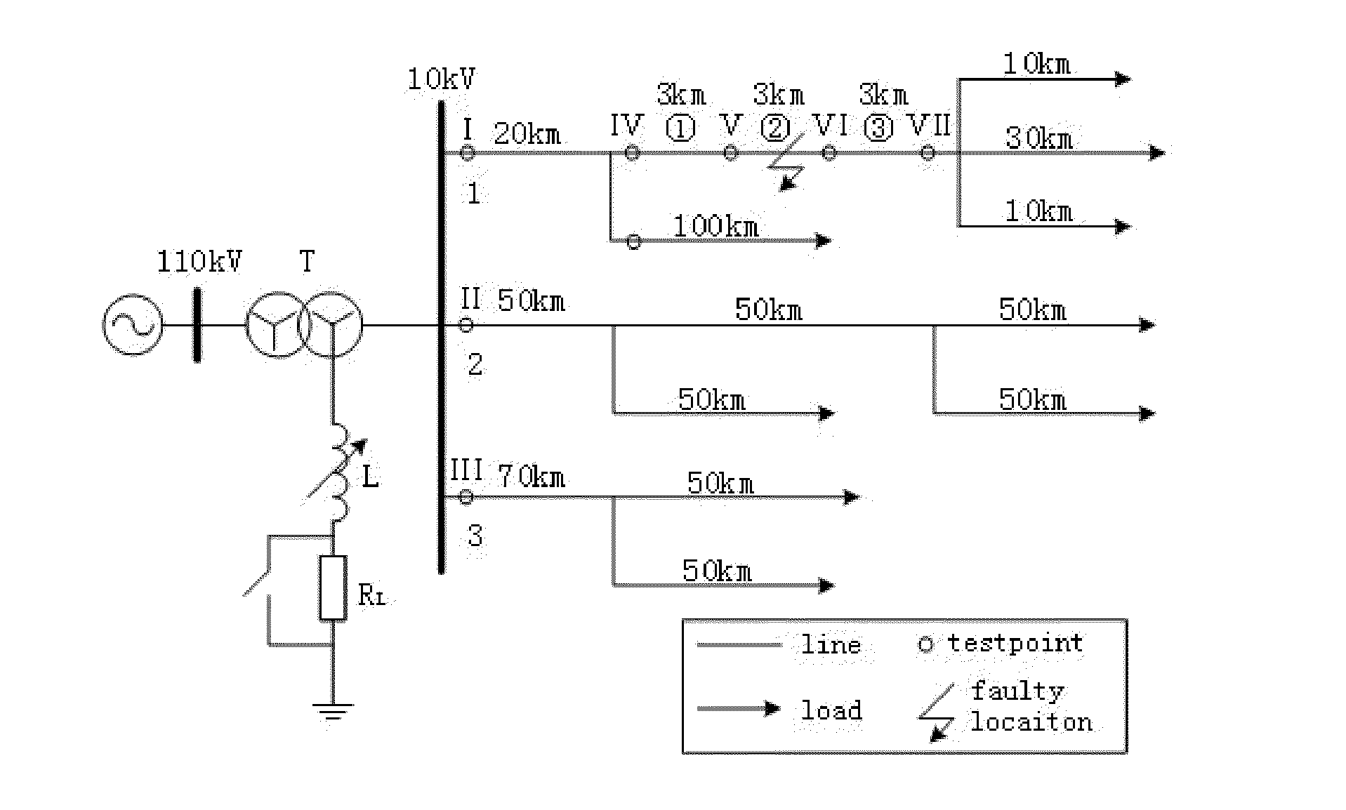
[0046]Step 1 (S1): the three-phase current and zero-sequence voltage of the busbar are monitored, an over-current to the busbar appears while the zero-sequence voltage is zero, where the over-current to phases A and B occurs and a current variation at 0.3s occurs; therefore, an AB inter-phase fault occurring at 0.3s is determined.

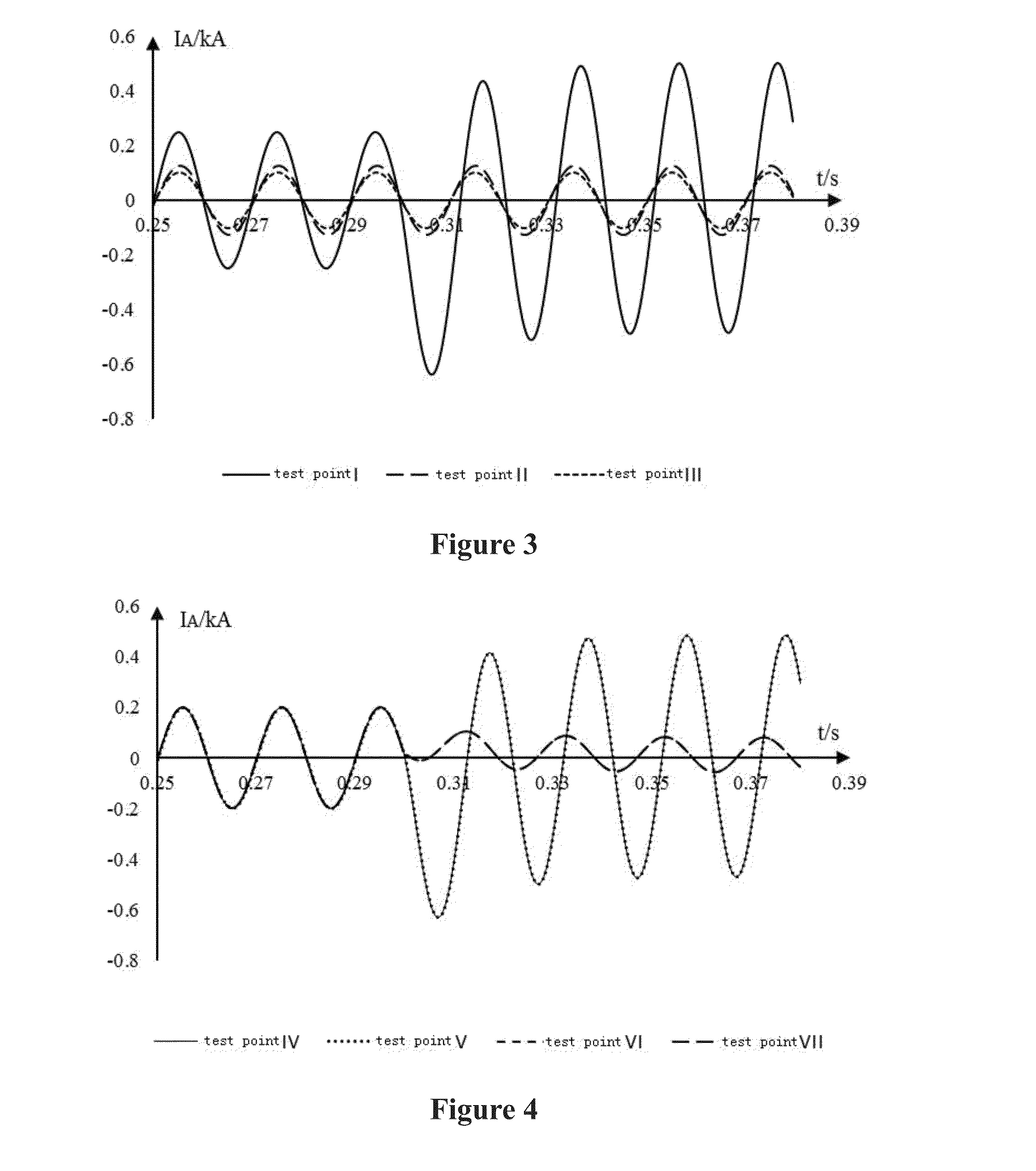
[0047]Step 2 (S2): fault-phase current to the detection points I, II and III are measured at the initial end of the three lines. As shown in FIG. 3, an over-current obviously occurs on the fault-phase current at the initial end of line 1, exceeding the preset value, while the fault-phase current to the initial ends of lines 2 and 3 remains unchanged. Therefore, line 1 is determined to be faulty.

[0048]Step 3 (S3): fault-phase current at detection points IV, V, VI and VII are measured along line 1 as shown in FIG. 4...

example 2

Detection and Location of the Grounding Fault

[0049]In the example of having a grounding fault, the method of the present invention provides that:

[0050]Step 1 (S1): three-phase current and zero-sequence voltage to the busbar are monitored, the zero-sequence voltage exceeds the phase voltage by 10% while there is no over current on the three-phase current to the busbar; zero-sequence voltage at 0.3s has a sudden change, thus, a grounding fault is determined at the moment of 0.3s.

[0051]Step 2 (S2): zero-sequence current and zero-sequence voltage at detection points I, II and III at the initial ends of the three lines are measured. As shown in FIGS. 5 and 6, the maximum values of the cross correlation function of the zero-sequence current and zero-sequence voltage at the three detection points are calculated, which are the time delays of the zero-sequence current corresponding to the zero-sequence voltage. As shown in Table 2., the maximum value of the cross correlation function of the ...


PUM


Abstract

A method for detecting and locating faulty line on the distribution network circuit based on full waveform information, which uses the current data on the fault occurrence and whole-process operation of the compensation device to effectively solve such common problems as low fault current, poor reliability and low sensitivity in case of single-phase grounding fault to the low-current system through precise GPS synchronization. It improves the sensitivity and reliability of the grounding fault detection, which does not interfere with the system and is applicable to high-resistance grounding.

Description

CROSS-REFERENCE AND RELATED APPLICATIONS[0001]The subject application claims priority on Chinese patent application No. CN 201410437624.X filed on Aug. 29, 2014. The contents and subject matter of the Chinese priority application is incorporated herein by reference.FIELD OF THE INVENTION[0002]The present invention relates to a method for diagnosing faulty line on the electrical power distribution network, particularly, the method is based on full waveform information for locating the circuit fault on the distribution network.BACKGROUND OF THE INVENTION[0003]During the operation of the electrical power system, power failure due to the distribution network faults statistically accounts for over 95% of the total accidents, and 70% of the accidents are caused by single-phase grounding faults or busbar faults. To avoid power failure when the single-phase grounding fault occurs, non-effective grounding (low-current grounding) mode at the neutral points of the external distribution network...

Claims


Application Information

Patent Timeline
IPC IPC(8): G01R31/02G01R31/08H02H3/08H02H7/22
CPCG01R31/025G01R31/088H02H3/083H02H7/22G01R31/086G01R31/52H02H7/261H02H7/28
Inventor LIU, YADONGSHENG, GEHAODAI, JIEJIELIU, JIAMEIHU, YUNXIE, XIAOLEIQIAN, YONGHU, YUEJIANG, XIUCHEN
Owner SHANGHAI JIAO TONG UNIV
Why Eureka
Try Eureka