Ribbed large-format imprinted structure

a large-format, imprinted technology, applied in the direction of dielectric characteristics, instruments, photomechanical equipment, etc., can solve the problems of difficult to uniformly fill expensive optical alignment equipment, and difficulty in uniformly filling a large imprinted area, so as to reduce material requirements, improve uniformity and size, and increase manufacturing speed

Inactive Publication Date: 2016-03-03
EASTMAN KODAK CO
View PDF4 Cites 2 Cited by
  • Summary
  • Abstract
  • Description
  • Claims
  • Application Information

AI Technical Summary

Benefits of technology

[0015]Structures and methods of the present invention provide color filters on a large fill-factor substrate and, more generally, provide filled large-format imprinted structures having improved uniformity and size using a process that decreases material requirement, increases manufacturing speed, and requires less material and equipment.

Problems solved by technology

This process is expensive and time consuming because it is a subtractive process that is wasteful of etched materials, uses additional, expensive materials such as photoresists and masks, and requires expensive optical alignment equipment.
However, as with the imprinting process itself, it is difficult to uniformly fill a large, imprinted area with a liquid that is subsequently cured.
For example, the coffee-ring effect is widely known to compromise the uniformity of a dried coating because of capillary flow induced by differential evaporation rates over the extent of the coating.
Therefore, because of such imprinting and drying problems, it is difficult to form large fill-factor substrates, such as color filter substrates, using imprint-and-fill processes.

Method used


Image

  • Ribbed large-format imprinted structure
  • Ribbed large-format imprinted structure
  • Ribbed large-format imprinted structure

Examples


Embodiment Construction

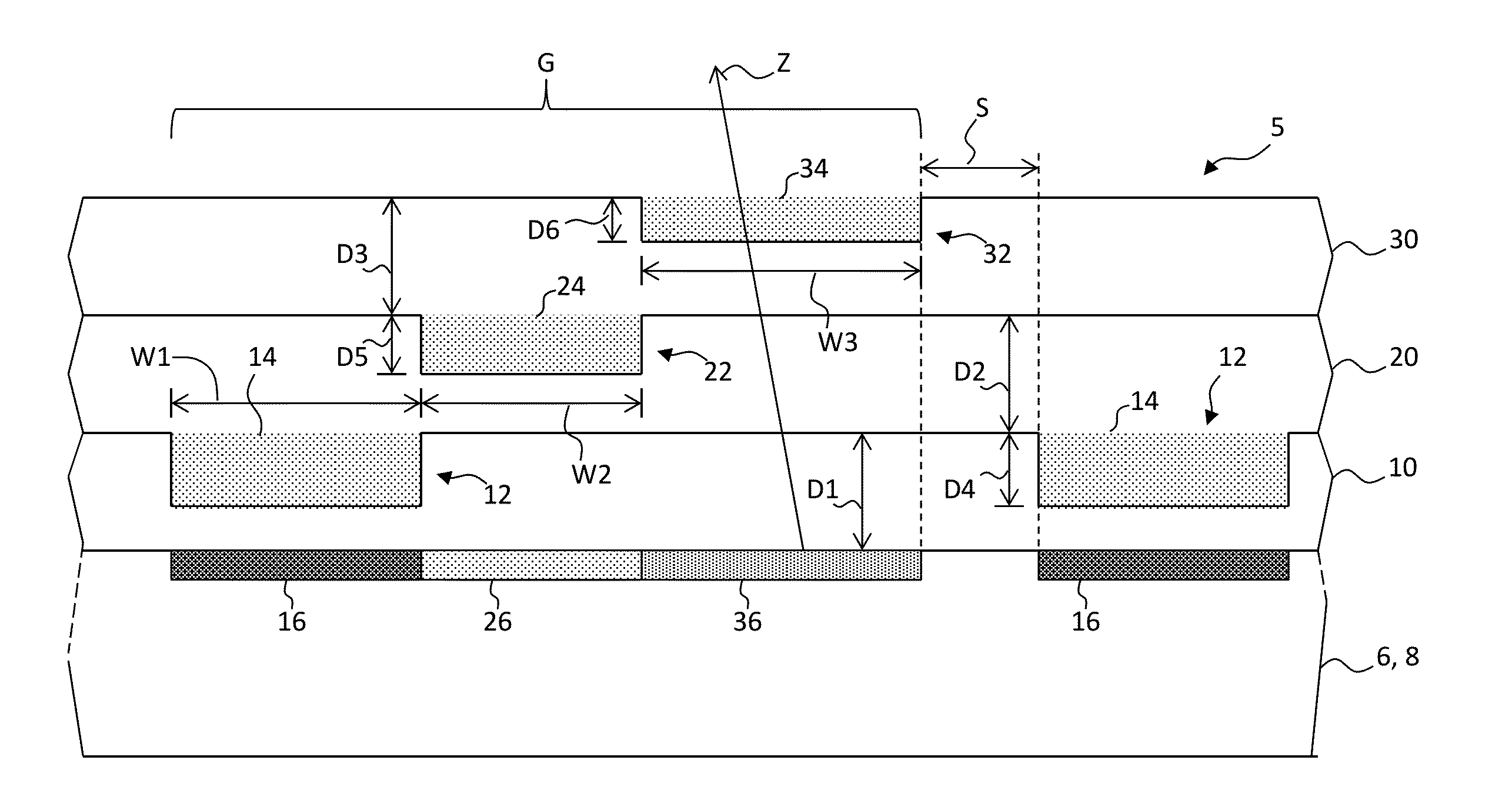
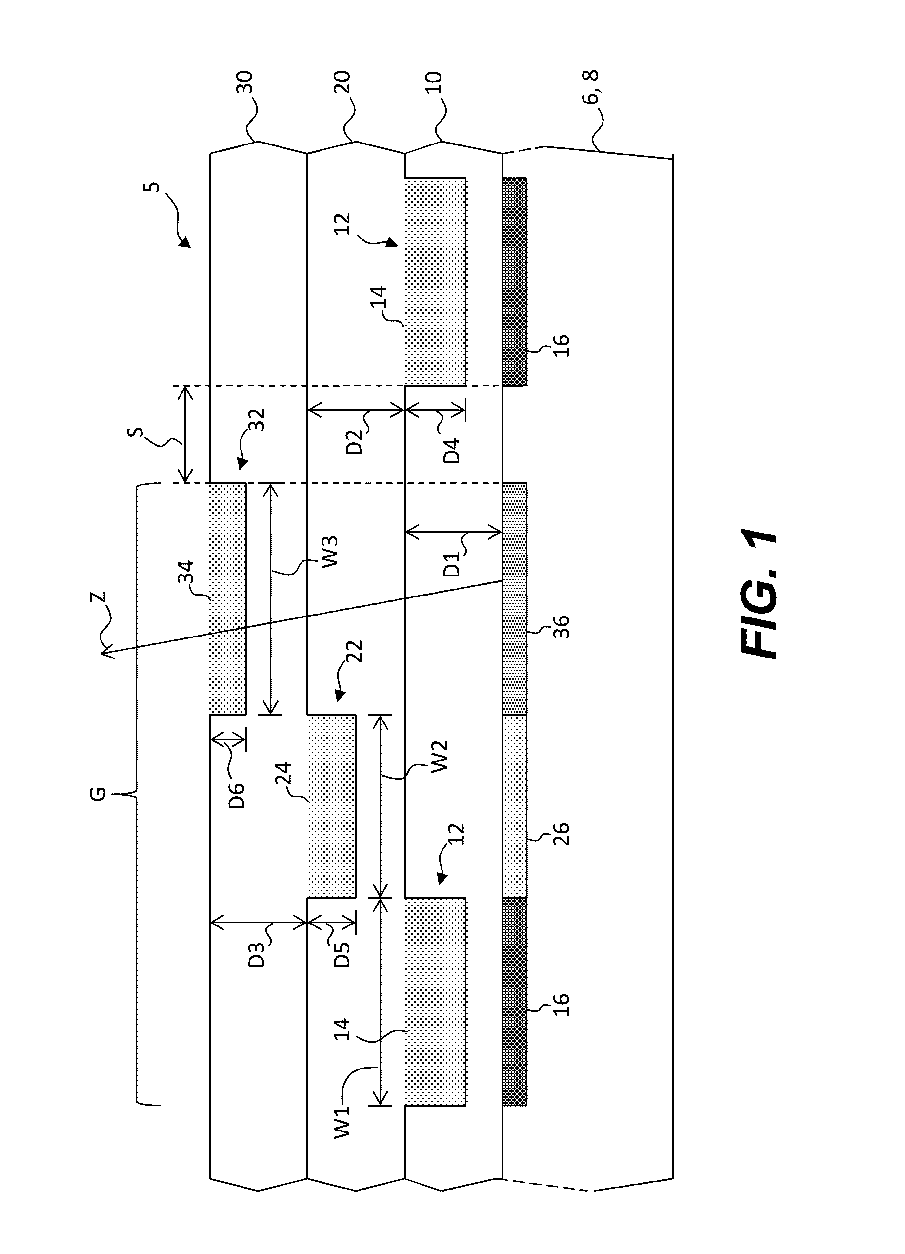
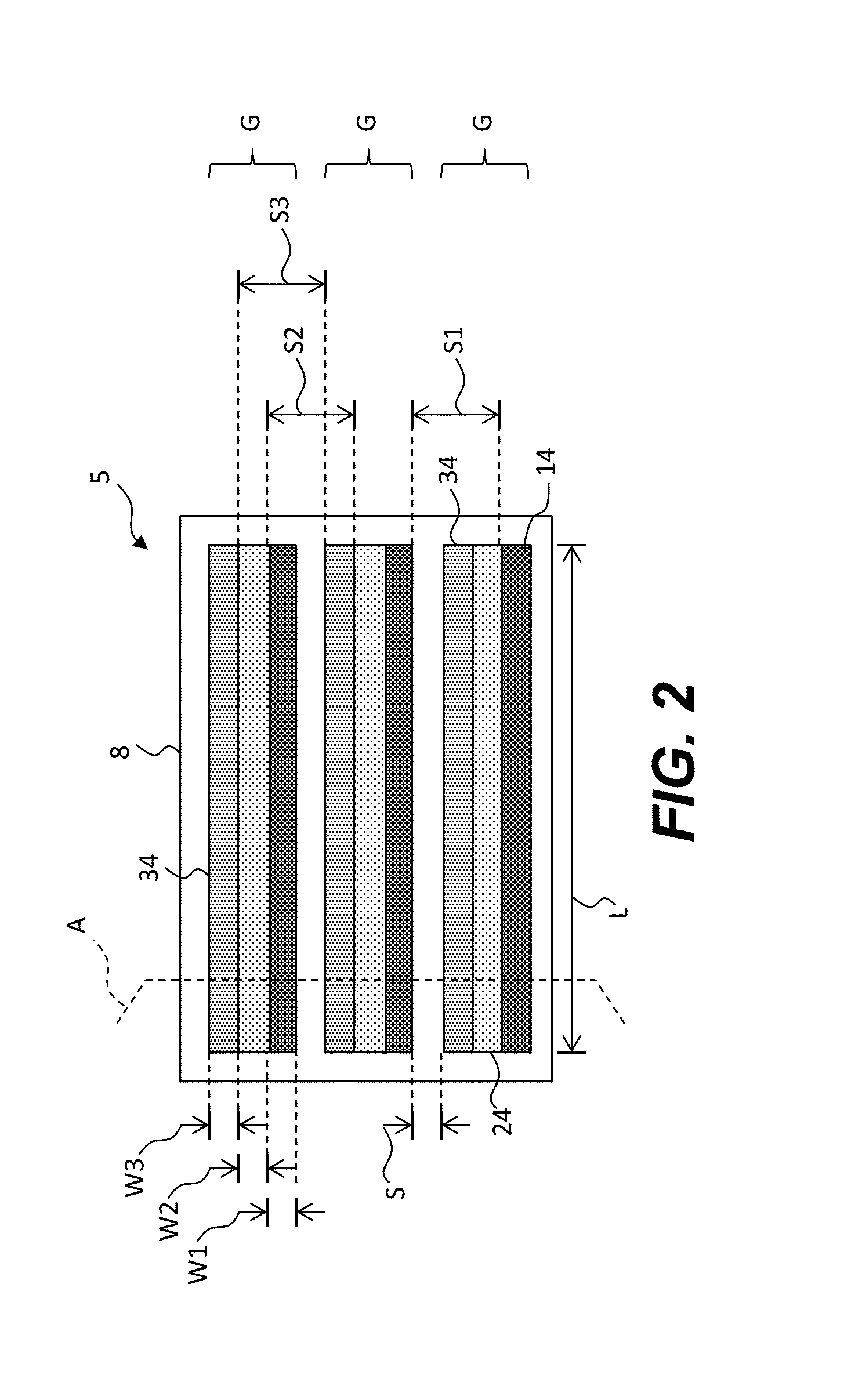
[0029]According to various embodiments and methods of the present invention, filled large-format imprinted structures such as color filters having improved uniformity and size are provided by using structures and processes that decrease material requirements, increase manufacturing speed, and require less equipment. As is described more fully below, imprinting processes form relief features or structures such as micro-cavities in a curable layer. Once the curable layer is cured, the micro-cavities are filled with a curable material and dried to form, for example, color filters. Multiple stacked cured layers, arrangements of micro-cavities in the stacked cured layers, and structures formed in the micro-cavities in the cured layers mitigate problems found in structures and methods of the prior art.

[0030]Additive imprinting processes are known to form small features such as micro-cavities in cured layers at a relatively high rate compatible with inexpensive roll-to-roll processes with ...


PUM

PropertyMeasurementUnit
widthaaaaaaaaaa
thicknessaaaaaaaaaa
sizeaaaaaaaaaa

Abstract

A filled large-format imprinted structure includes a cured layer including a cured layer surface and one or more micro-cavities imprinted in the cured layer, each micro-cavity having a micro-cavity width and a micro-cavity depth. One or more ribs are imprinted in each micro-cavity and extend from the bottom of the micro-cavity toward the top of the micro-cavity, each rib having a rib width that is less than one half of the micro-cavity width, and a rib height that is less than the micro-cavity depth. Each rib separates the micro-cavity into portions, each portion having a portion width less than or equal to 20 microns. A cured material is located in each portion of the micro-cavity and extends over the top of the rib, thereby defining a filled large-format imprinted structure.

Description

CROSS REFERENCE TO RELATED APPLICATIONS[0001]Reference is made to commonly-assigned U.S. patent application Ser. No. (Docket K001725) filed concurrently herewith, entitled Filled Large-Format Imprinted Structure by Cok; to commonly-assigned U.S. patent application Ser. No. (Docket K001727) filed concurrently herewith, entitled Filled Large-Format Imprinting Method by Cok; to commonly-assigned U.S. patent application Ser. No. (Docket K001729) filed concurrently herewith, entitled Ribbed Large-Format Imprinting Method by Cok; to commonly-assigned U.S. patent application Ser. No. (Docket K001730) filed concurrently herewith, entitled Multi-Layer Large-Format Imprinted Structure by Cok; to commonly-assigned U.S. patent application Ser. No. (Docket K001731) filed concurrently herewith, entitled Multi-Layer Large-Format Imprinting Method by Cok; to commonly-assigned U.S. patent application Ser. No. (Docket K001732) filed concurrently herewith, entitled Stacked Large-Format Imprinted Struc...

Claims


Application Information

Patent Timeline
Patent Type & Authority Applications(United States)
IPC IPC(8): G02F1/1335
CPCG02F1/133514G02B5/201G02F1/133516G02F2001/133519H05K1/092H05K1/111H05K2201/0108B29K2105/24B29C2035/0827B29C59/026B29C59/002B29C35/0805B29K2995/0021B29L2031/3475B29C59/022B29C2059/023G02B5/003G03F7/0007G02F2201/52G03F7/0002G02F1/133519
Inventor COK, RONALD, STEVEN
Owner EASTMAN KODAK CO
Why Eureka
Try Eureka