
Micro-fabricated integrated coil and magnetic circuit and method of manufacturing thereof

a micro-fabricated, integrated coil technology, applied in the direction of semiconductor devices, semiconductor/solid-state device details, inductances, etc., can solve the problems of structural discontinuities affecting flux loss, limiting the conventional fabrication process of such electromagnetic elements in size and density, and affecting the effect of flux loss, high efficiency, and high power density

Active Publication Date: 2016-03-03
TELEDYNE SCI & IMAGING
View PDF8 Cites 5 Cited by
  • Summary
  • Abstract
  • Description
  • Claims
  • Application Information

AI Technical Summary

Benefits of technology

The present invention is an electromagnetic device that includes a core and a coil integrated in a semiconductor substrate. The core has a width and a length along a longitudinal axis that is substantially greater than the width. The core defines a cavity along the longitudinal axis. The core includes a first magnetic layer and a second magnetic layer positioned parallel to the first magnetic layer. The core also includes an electrically insulating layer positioned between the first magnetic layer and the second magnetic layer. The insulating layer suppresses eddy currents flowing between the magnetic layers. The semiconductor substrate has a plurality of openings in which a coil is embedded. The coil has a portion parallel to the longitudinal axis and positioned in the cavity. An insulating material is positioned in the cavity and between the coil and the inner surface of the core. The insulating material electrically insulates the core from the coil and reduces stress from a thermal expansion mismatch between the coil and the core. The electromagnetic device structure provides a closed loop flux path substantially free of bunching and spreading, high power density, high efficiency, and favorable transient response.

Problems solved by technology

Conventional fabrication processes of such electromagnetic elements have been limiting in terms of size and density.
Because cores known in the art have been commonly manufactured with multiple low-frequency magnetic components, power loss and parasitics are significant.
Furthermore, micro-scale cores known in the art that provide closed magnetic flux path have structural discontinuities that impact flux loss.
The micro-scale cores known in the art are also susceptible to flux bunching and spreading.
Micro-scale magnetic elements known in the art do not perform optimally under high frequencies and are therefore unsuitable for integration in power converter circuits (e.g., DC-DC converters).
Furthermore, mirco-scale magnetic elements have poor transient responses.
The poor transient response is unsuitable for integration in power amplifiers of envelope tracking circuitry in which bias voltage is dynamically adjusted at a high frequency.

Method used


Image

  • Micro-fabricated integrated coil and magnetic circuit and method of manufacturing thereof
  • Micro-fabricated integrated coil and magnetic circuit and method of manufacturing thereof
  • Micro-fabricated integrated coil and magnetic circuit and method of manufacturing thereof

Examples


Embodiment Construction

[0040]Apparatus, systems and methods that implement the implementation of the various features of the present disclosure will now be described with reference to the drawings. The drawings and the associated descriptions are provided to illustrate some implementations of the present disclosure and not to limit the scope of the present disclosure. Throughout the drawings, reference numbers are re-used to indicate correspondence between reference elements. In addition, the first digit of each reference number generally indicates the figure in which the element first appears.

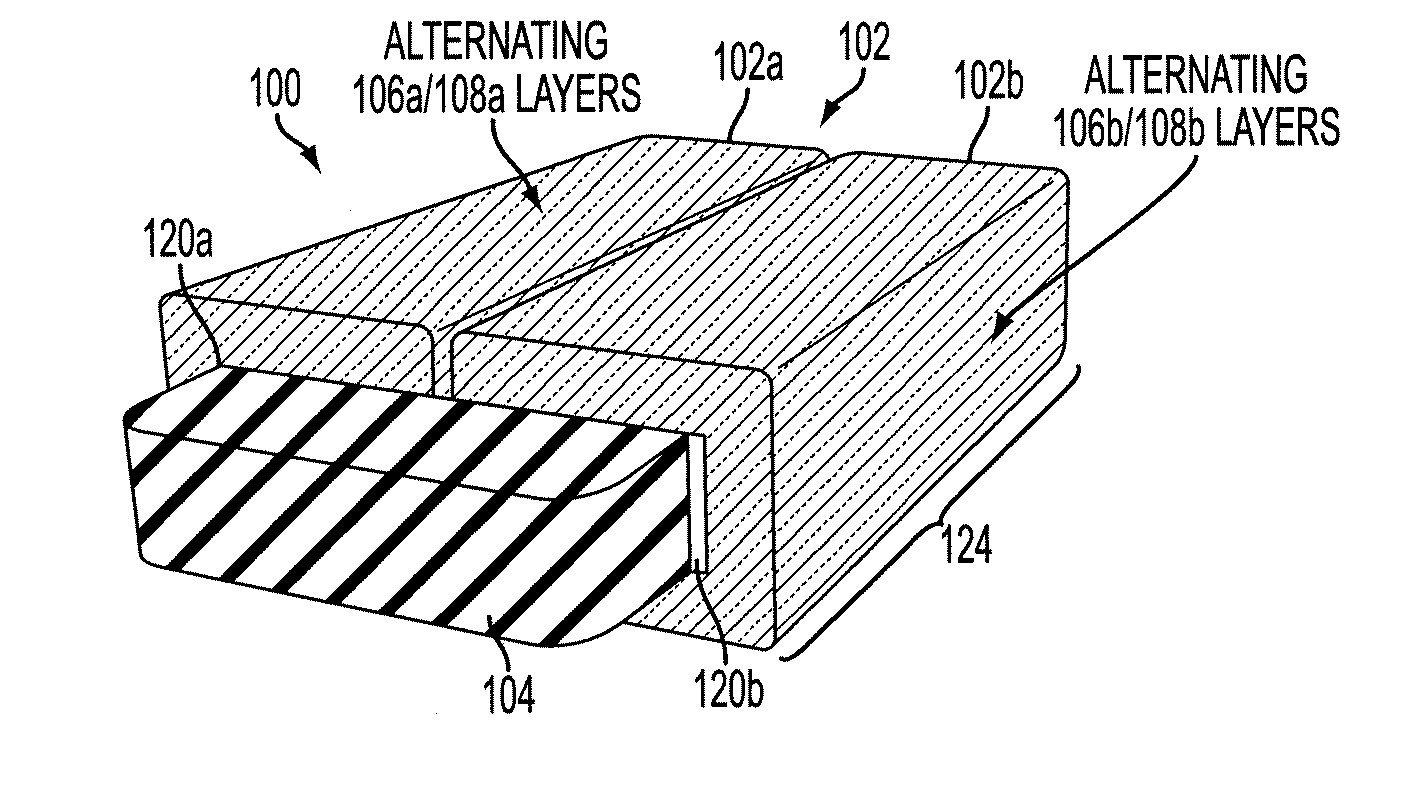
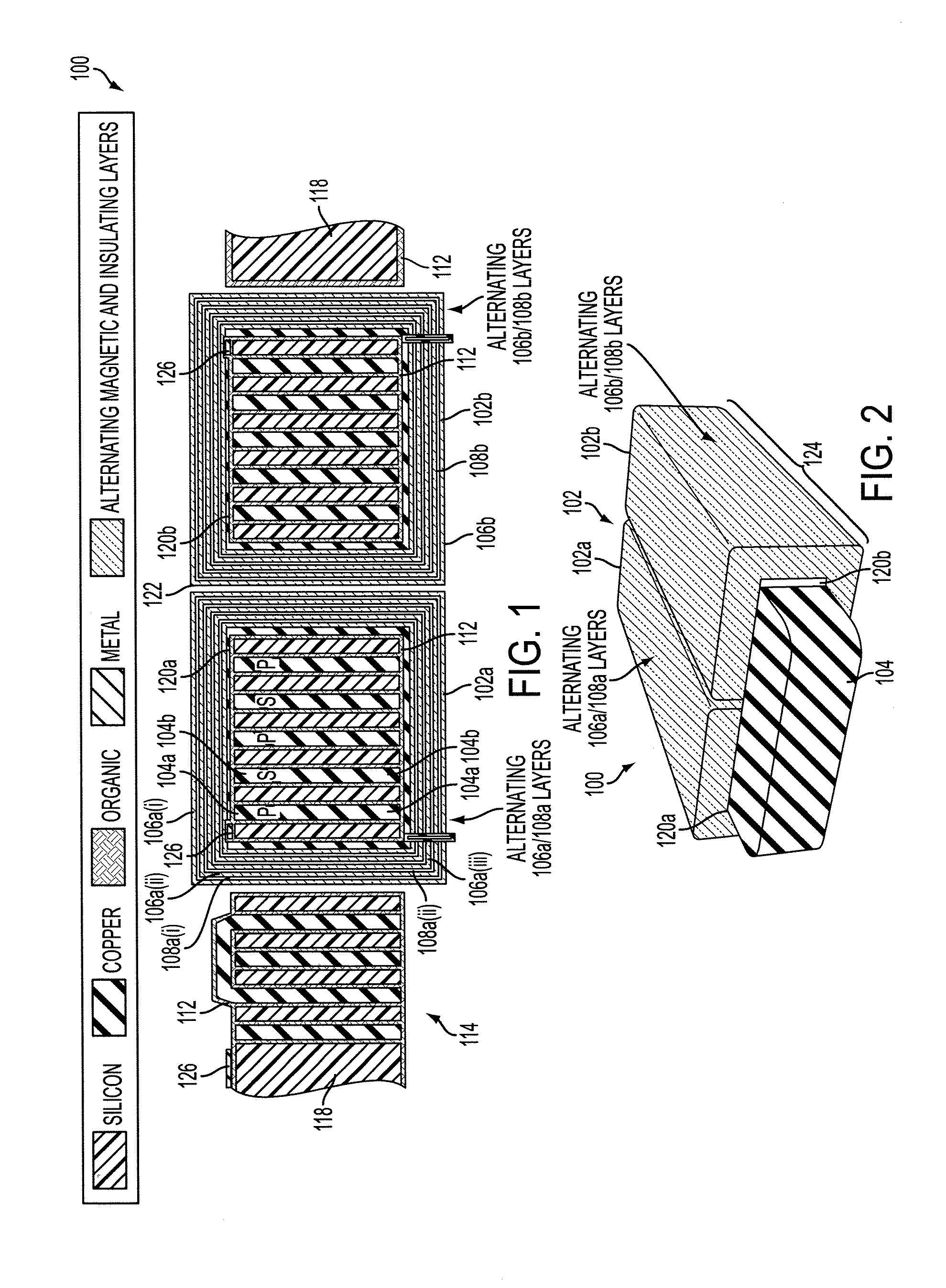
[0041]FIG. 1 is a cross-section schematic view of an electromagnetic device 100 having a core unit 102 and a coil 104 embedded in a semiconductor substrate 118. FIG. 2 is a perspective schematic view of the electromagnetic device 100 shown in FIG. 1. The electromagnetic device 100 may be a transformer or a portion thereof. The electromagnetic device 100 may have a core unit 102 which may include a first core 102a an...


PUM


Abstract

A micro-fabricated electromagnetic device is provided for on-circuit integration. The electromagnetic device includes a core. The core has a plurality of electrically insulating layers positioned alternatingly between a plurality of magnetic layers to collectively form a continuous laminate having alternating magnetic and electrically insulating layers. The electromagnetic device includes a coil embedded in openings of the semiconductor substrate. An insulating material is positioned in the cavity and between the coil and an inner surface of the core. A method of manufacturing the electromagnetic device includes providing a semiconductor substrate having openings formed therein. Windings of a coil are electroplated and embedded in the openings. The insulating material is coated on or around an exposed surface of the coil. Alternating magnetic layers and electrically insulating layers may be micro-fabricated and electroplated as a single and substantially continuous segment on or around the insulating material.

Description

STATEMENT REGARDING GOVERNMENT RIGHTS[0001]This invention was made with Government support under Government Contract Reference No. DE-AR0000113 awarded by Advanced Research Projects Agency—Energy of U.S. Department of Energy. The Government has certain rights in this invention.BACKGROUND[0002]1. Field[0003]The present disclosure relates to integrated and micro-fabricated magnetic circuits and methods of manufacturing thereof.[0004]2. Description of the Related Art[0005]Electromagnetic devices, such as inductors, transformers, and various other electromagnetic devices, utilize coils that pass through a cavity of a magnetic core. Conventional fabrication processes of such electromagnetic elements have been limiting in terms of size and density. Because cores known in the art have been commonly manufactured with multiple low-frequency magnetic components, power loss and parasitics are significant. Furthermore, micro-scale cores known in the art that provide closed magnetic flux path ha...

Claims


Application Information

Patent Timeline
IPC IPC(8): H01L49/02
CPCH01L28/10H01F17/0013H01F2017/0066H01F2017/0086H01L23/645H01L23/00
Inventor MIHAILOVICH, ROBERT, E.PAPAVASILIOU, ALEX, P.MEHROTRA, VIVEKSTUPAR, PHILIP, A.BORWICK, III, ROBERT, L.GANGULI, RAHULDENATALE, JEFFREY, F.
Owner TELEDYNE SCI & IMAGING
Learn More