

Buck converter with a stabilized switching frequency
a technology of switching frequency and buck converter, which is applied in the direction of ac network voltage adjustment, efficient power electronics conversion, electric variable regulation, etc., can solve the problems of increasing losses, causing losses, and causing losses, and achieve the effect of eliminating switching losses
- Summary
- Abstract
- Description
- Claims
- Application Information
AI Technical Summary
Benefits of technology
Problems solved by technology
Method used
Image

Examples
Embodiment Construction
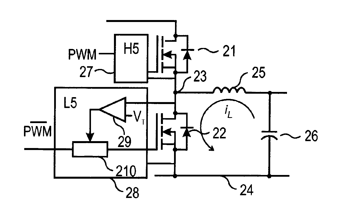
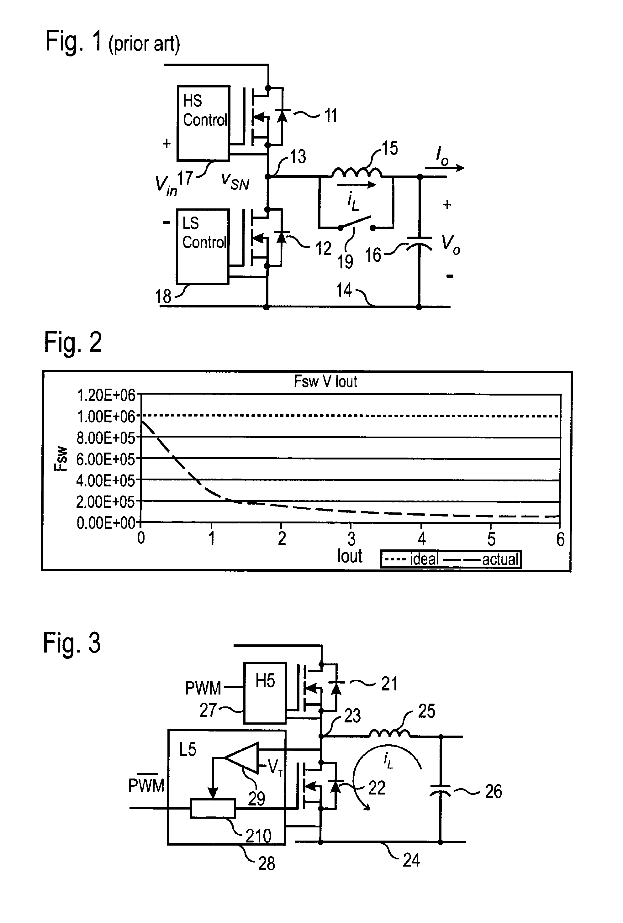
[0033]FIG. 3 shows a SBCM buck converter comprising an output stage with a non-linear inductor 25 and a capacitor 26. The output stage generates an output voltage according to a control signal and an input voltage. The switchable buck converter comprises a high-side switch 21 and a low-side switch 22, each having respective first and second main terminals and a respective control terminal driven by a respective driver 27, 28 configured according the control signal. The control signal is a pulse width modulation signal. A drive signal of the high-side switch 21 corresponds to the PWM signal and the drive signal of the low-side switch 22 corresponds to the complement of the PWM signal. The first low-side main terminal is connected to ground. The second low-side main terminal and the first high-side main terminal are connected to a switch node 23. The second high-side main terminal is connected to an input voltage terminal. The output stage comprises the non-linear inductor 25 connecte...
PUM
 Abstract
Description
Claims
Application Information