
Valved aortic conduits

a valve and aortic valve technology, applied in the field of valved aortic valves and aortic conduits, can solve the problems of high leakage rate, too much blood entering the valve walls, and heart valve disease remains a significant cause of morbidity and mortality, and achieve the effect of facilitating a redo operation

Active Publication Date: 2016-03-10
EDWARDS LIFESCIENCES CORP
View PDF15 Cites 81 Cited by
  • Summary
  • Abstract
  • Description
  • Claims
  • Application Information

AI Technical Summary

Benefits of technology

The patent text describes a valved conduit containing a bioprosthetic heart valve and a tubular conduit graft. The conduit graft can be attached to the heart valve in different ways to allow for a redo operation in which the valve is replaced. The heart valve may be made of bioresorbable material that can be stored dry for extended periods without degrading its function. The attachment configuration facilitates a simple operation in which the valve can be easily excised from within the graft and replaced. The technical effects of this invention include simplified assembly and creation of a secure and reliable connection between the heart valve and the conduit graft.

Problems solved by technology

Heart valve disease continues to be a significant cause of morbidity and mortality, resulting from a number of ailments including rheumatic fever and birth defects.
Although such conduits are suitable in certain situations, and tend to seal relatively quickly in the body from tissue ingrowth, too much blood can initially seep through their walls after implant which may be detrimental.
Uncoated fabric such as polyethylene terephthalate (PET) has a high leakage rate, and thus the surgeon needs to pre-clot the graft with patient's blood before use.
Nevertheless, such grafts still produce unacceptable leaking.
Others have proposed using a non-bioresorbable sealant layer, such as silicone in U.S. Patent Publication No. 2008 / 0147171 to Ashton, et al., published Jun. 19, 2008, but such layered conduits tend to be relatively thick walled and not very flexible, and so are not preferred.
Unfortunately, it is not possible to pre-assemble conduits or grafts sealed using bioresorbable materials with bioprosthetic heart valves because of storage complications.
Unfortunately, many of the prior valved conduit designs are so integrated that the entire assembly must be removed, rather than just the non-functioning valve.

Method used


Image

  • Valved aortic conduits
  • Valved aortic conduits
  • Valved aortic conduits

Examples


Embodiment Construction

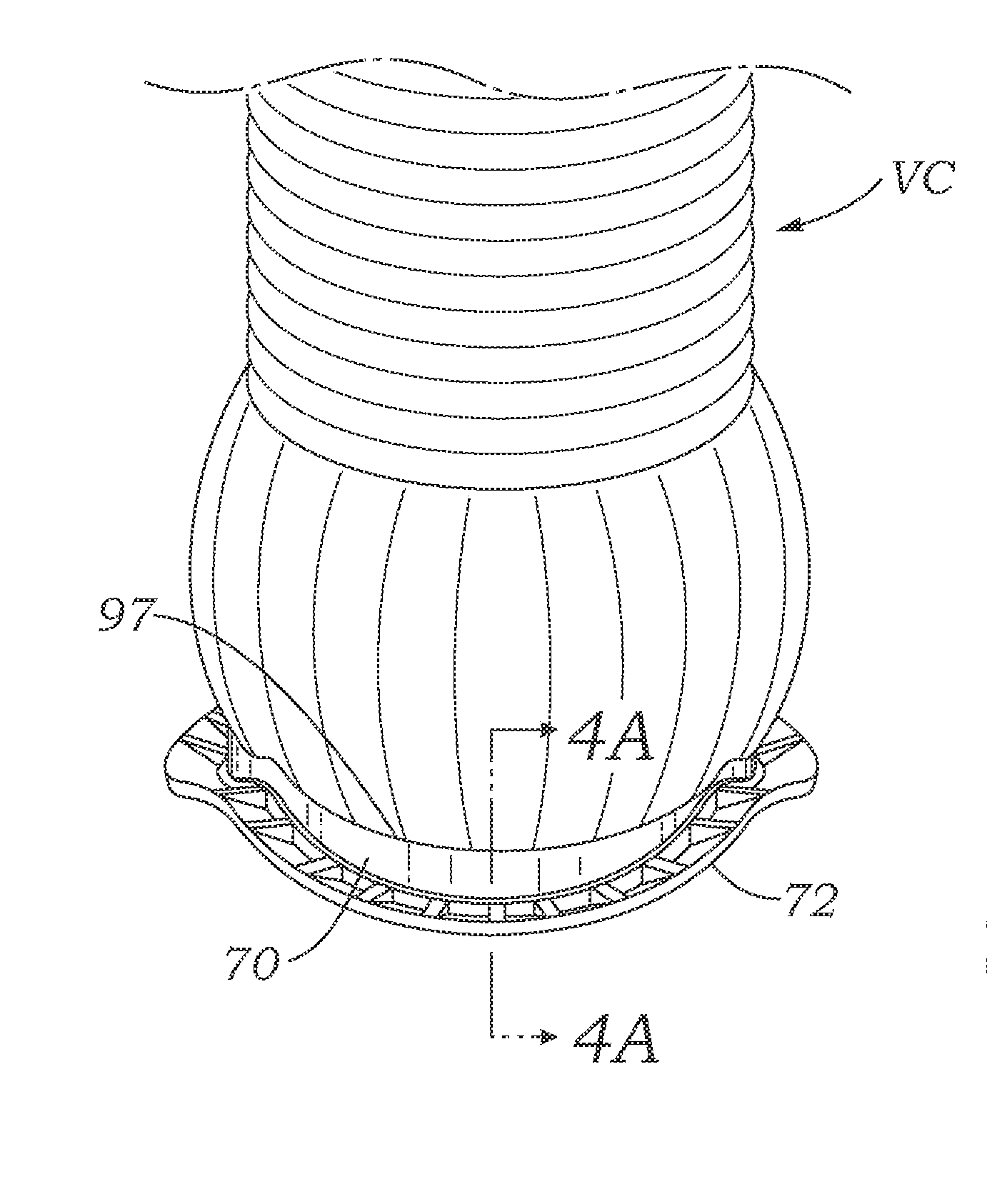
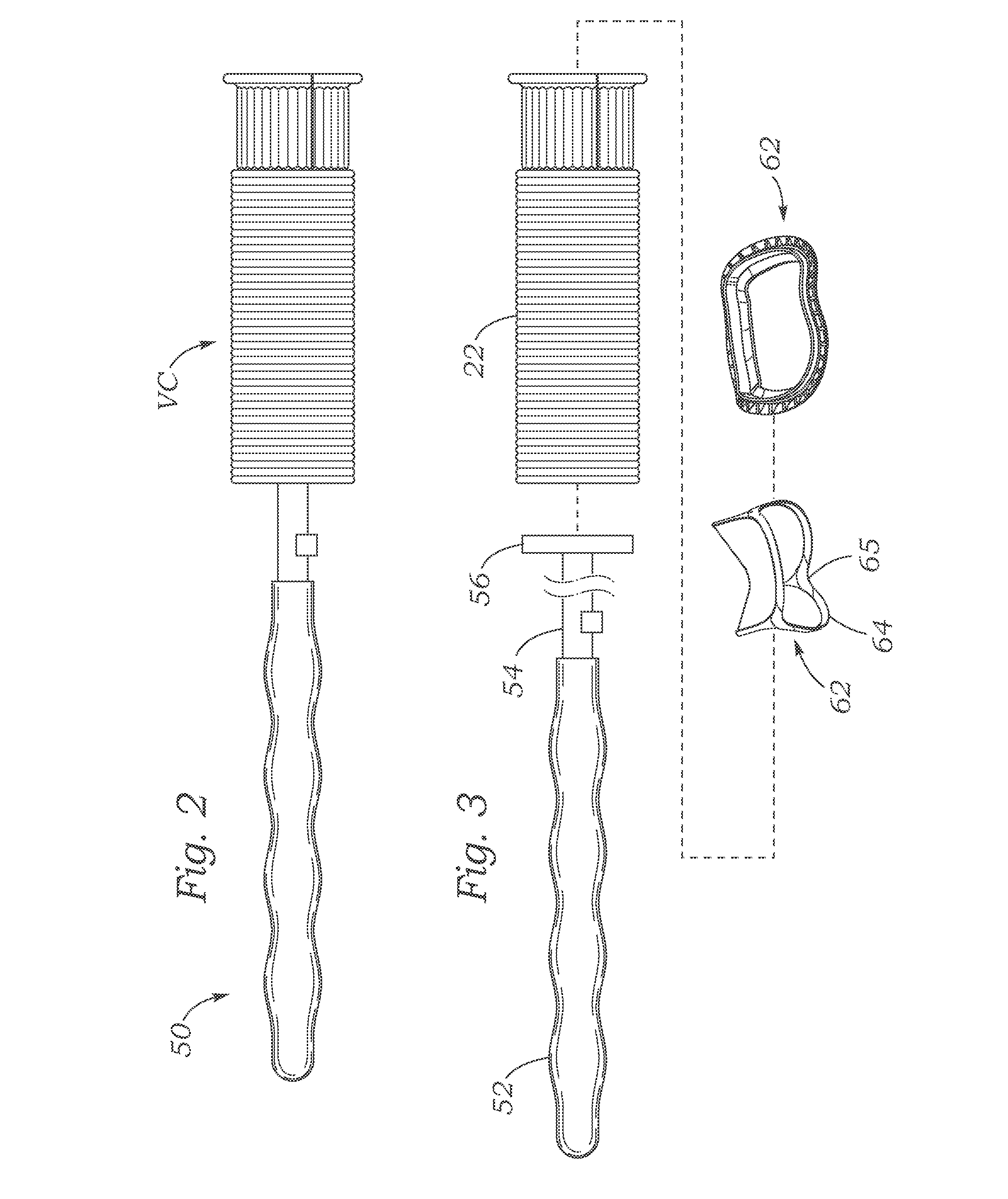
[0063]Described herein are a number of two-piece valved conduits including a prosthetic heart valve and a conduit graft that facilitate valve redo operations. That is, the heart valve within the valved conduit sometimes becomes calcified and must be replaced. The combinations disclosed herein provide easy to remove valves.

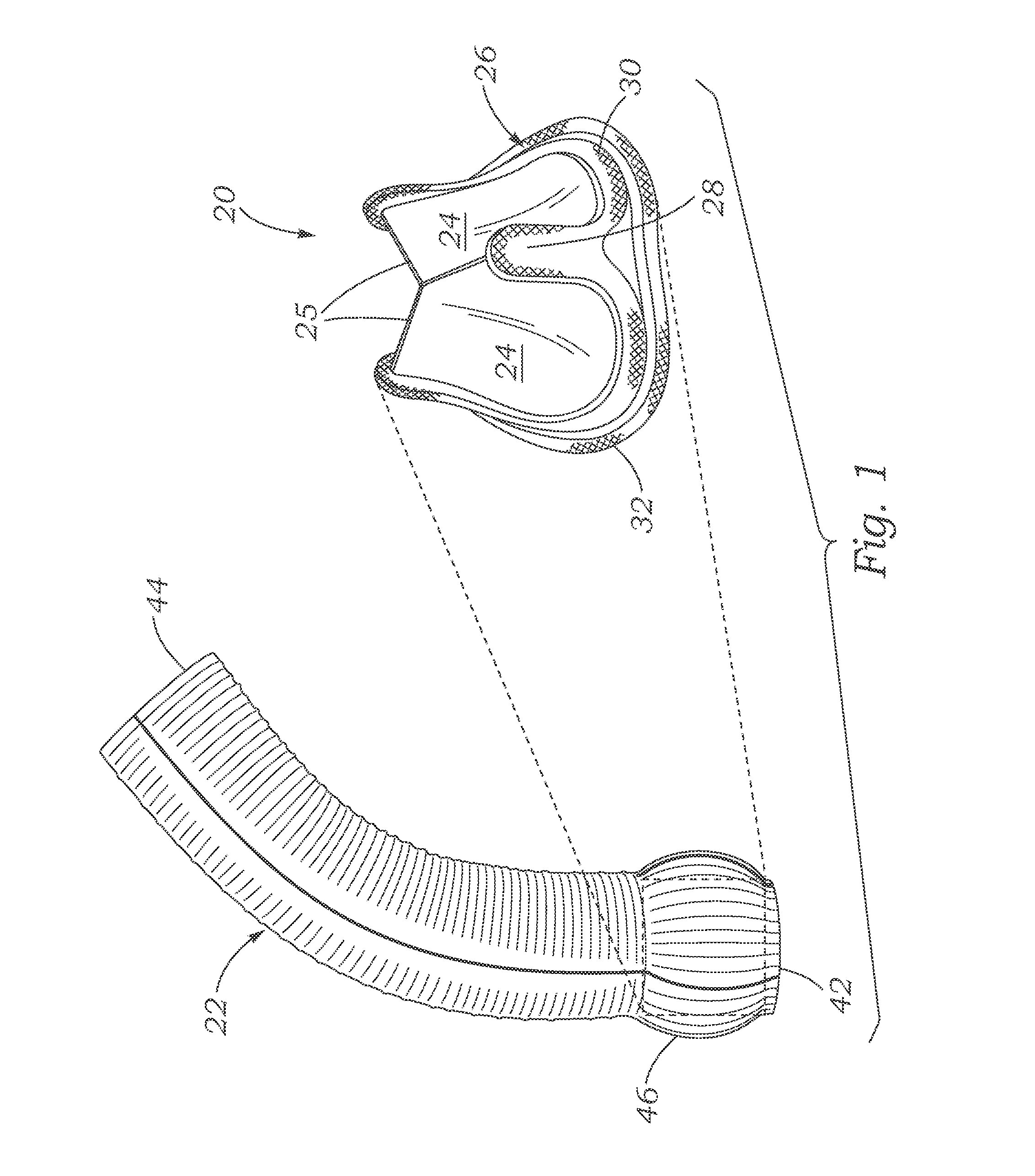
[0064]FIG. 1 is an exploded view of an exemplary valved conduit VC comprising the combination of a bioprosthetic heart valve 20 coupled to an aortic conduit graft 22. As suggested schematically, the prosthetic heart valve 20 is positioned within one end of the conduit graft 22. Such a valved conduit VC may be used for replacing a native aortic valve and the ascending aorta. Of course, certain principles disclosed herein would also apply to replacement of the pulmonary valve and the pulmonary artery.

[0065]The heart valve 20 includes a rigid or semi-rigid stent supporting a plurality of flexible leaflets 24 (typically three) that are mounted to a peripheral stent str...


PUM

PropertyMeasurementUnit
Circumferenceaaaaaaaaaa
Bioabsorbableaaaaaaaaaa

Abstract

A valved conduit including a bioprosthetic aortic heart valve connected to a tubular conduit graft forming an ascending aorta. The conduit graft may attach to the heart valve in a manner that facilitates a redo operation in which the valve is replaced with another valve. A sewing ring may be pre-attached to the inflow end of the graft, and then the valve connected to a delivery holder advanced into the graft and secured to the sewing ring. Dry bioprosthetic valves coupled with conduit grafts sealed with a bioresorbable medium can be stored with the delivery holder.

Description

RELATED APPLICATIONS[0001]This application is a continuation of International Patent Application No. PCT / US2014 / 030639, filed Mar. 17, 2014, which was published in English as International Patent Publication No. WO 2014 / 145811 A1 on Sep. 18, 2014, which claims the benefit U.S. Patent Application No. 61 / 802,201, filed Mar. 15, 2013, the entire disclosures of which are incorporated by reference herein.FIELD OF THE INVENTION[0002]The present invention generally relates to a prosthetic heart valve assembled with a flow conduit and, more particularly, to a pre-assembled aortic heart valve and aortic conduit that facilitates a redo operation wherein the valve is replaced with another valve.BACKGROUND OF THE INVENTION[0003]Heart valve disease continues to be a significant cause of morbidity and mortality, resulting from a number of ailments including rheumatic fever and birth defects. Cardiovascular disease is the number one cause of death, killing more than 600,000 Americans each year. Ac...

Claims


Application Information

Patent Timeline
IPC IPC(8): A61F2/24
CPCA61F2/2445A61F2240/001A61F2/2409A61F2/06A61F2/2427A61F2230/0076A61F2230/0095A61F2250/006A61F2/2412
Inventor MURAD, MICHAEL C.FANN, HILDA Z.VAN NEST, MARKWANG, JOHN X.
Owner EDWARDS LIFESCIENCES CORP
Learn More