
Eureka
For R&D, Eureka makes reading and utilizing patents & technical documents easy.
Eureka AIR
Designed for self-driven R&D workflows. Generate viable solutions, solve complex R&D challenges, empower your innovation with AI.

Eureka Materials
Designed for material experts only. Revolutionize your material R&D, from search, analyze, to developing new materials.

TechResearch
Generate reliable direction feasibility study reports for your R&D in just a few steps.

TechSeek
Discover and master advanced knowledge NOW. Basics, ideas, possibilities, all at once.

TechMind
As an expert in R&D Theories, TechMind can generates customized viable solutions instantly.

TechRisk
Analyze your overall solution with one click, know your potential R&D risks in advance.

TechMonitor
Get weekly tech updates, stay abreast of the latest tech innovations and key insights.
Apparatus and process for packaging a product
- Summary
- Abstract
- Description
- Claims
- Application Information
AI Technical Summary
Benefits of technology
Problems solved by technology
Method used
Image

Examples
first embodiment
of the Apparatus 1
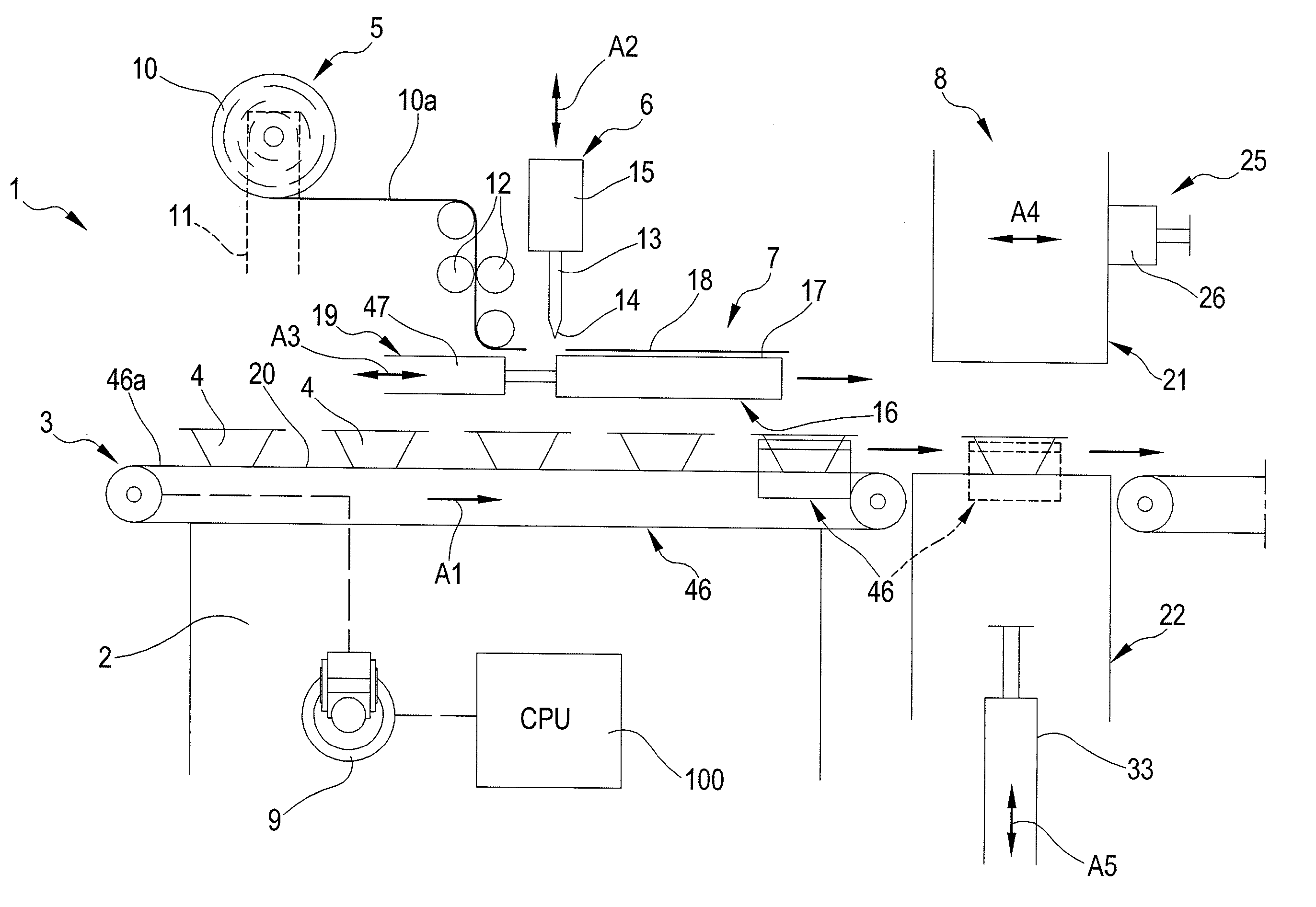
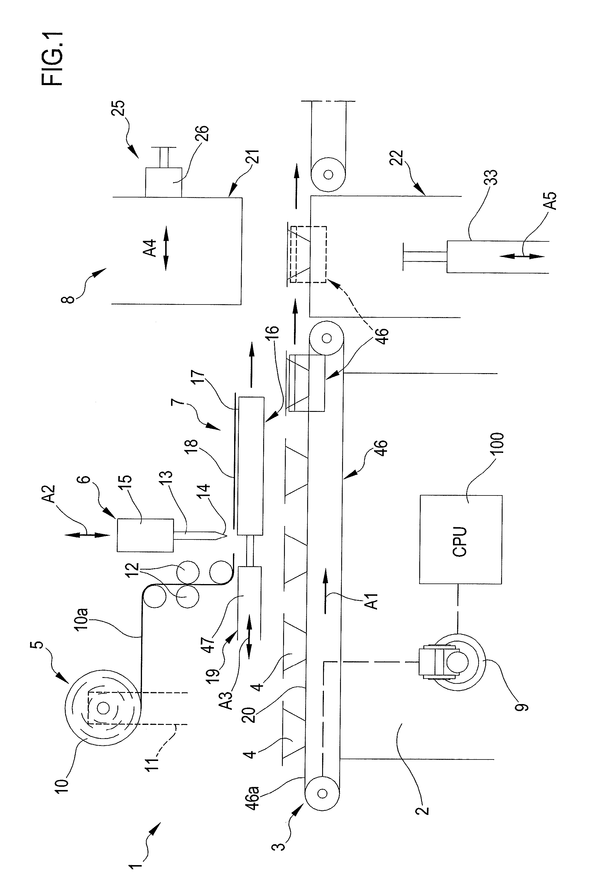
[0209]FIGS. 1-8 show an apparatus 1 for packaging of a product P arranged on a support or tray 4 according to an embodiment of the present invention. The apparatus 1 is adapted for modified atmosphere packaging, where a plastic film, such as film sheet 18 described below, is applied to the top rim 4c of a support or tray 4 after a modified gas atmosphere has been created inside the support 4, and / or for vacuum skin packaging of the product P, where a thin film of plastic material, such as film sheet 18 described below, is draped down on the product and intimately adheres to a top rim and to the inner surface of the support as well as to the product surface thus leaving a minimum, if any, amount of air within the packaging. The apparatus 1 may also be used in case a film sheet applied to a tray or support and neither vacuum nor modified atmosphere is created.
[0210]The apparatus 1 comprises a frame 2, a transport assembly 3 for displacing the support or tray 4, a fil...
second embodiment
of the Apparatus 1
[0263]In FIGS. 9-12 a second embodiment of apparatus 1 is shown. The general structure of FIG. 1 may also apply to this second embodiment. For sake of conciseness only the aspects and components of this second embodiment differing from those of the first embodiment will be described; the remaining aspects and components are the same as in the first embodiment and have been identified with same reference numerals. The differences with respect to the first embodiment concern the packaging assembly: in the case of FIGS. 9-11 the packaging assembly 8 comprises at least a side wall 42 movably associated to one of the upper tool 21 or lower tool 22. In the example illustrated in FIG. 9, the side wall 42 is associated to lower tool 22 and tightly slides along direction A5 (e.g. vertically) in correspondence of the lateral surface of the lower tool. The side wall may be a single side wall or may be formed by a plurality of side walls, each one acting on a respective side o...
third embodiment
of the Apparatus 1
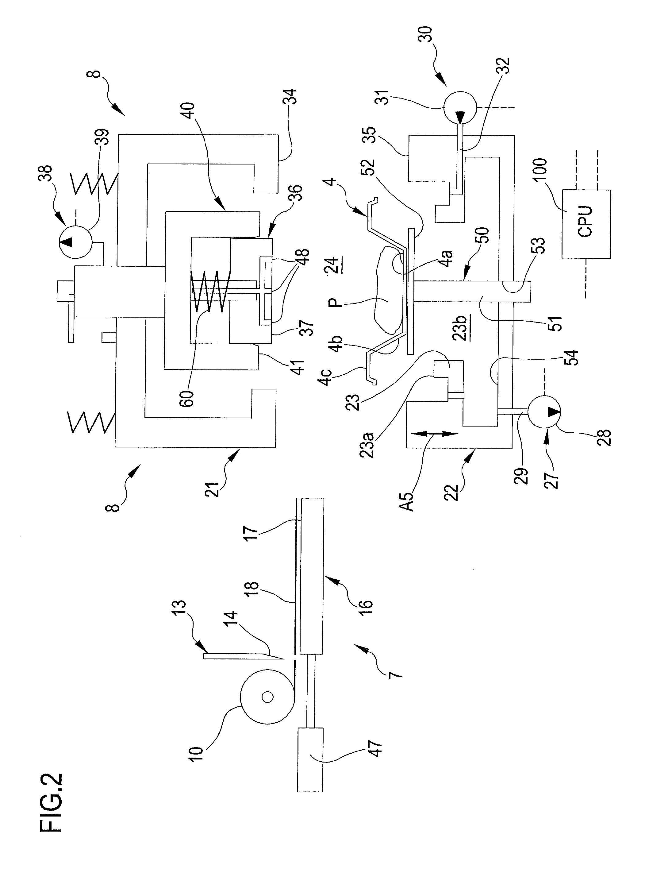
[0278]In FIGS. 12-16 a third embodiment of apparatus 1 is shown. For sake of conciseness only the aspects and components of this second embodiment differing from those of the first embodiment will be described; the remaining aspects and components are the same as in the first embodiment and have been identified with same reference numerals. The differences with respect to the first embodiment concern the packaging assembly: in the case of FIGS. 12-16 the upper tool 21 has at least one holding plate 36 having a respective active surface 37: the holding plate 36 is terminally carried by shaft 36a and covers the entire radial span of the end surface 23a and thus also of rim 4c. The holding plate shaft is coupled to the upper tool 21 to allow at least movement along direction of double arrow A5 as it will be explained herein below. The means 38 for holding may comprise a vacuum source 39, e.g. in the form of a pump, controlled by the control unit 100 and connected to a...
PUM
| Property | Measurement | Unit |
|---|---|---|
| Temperature | aaaaa | aaaaa |
| Temperature | aaaaa | aaaaa |
| Temperature | aaaaa | aaaaa |
Abstract
Description
Claims
Application Information
 - R&D Engineer
- R&D Manager
- IP Professional
- Industry Leading Data Capabilities
- Powerful AI technology
- Patent DNA Extraction
Browse by: Latest US Patents, China's latest patents, Technical Efficacy Thesaurus, Application Domain, Technology Topic, Popular Technical Reports.
© 2024 PatSnap. All rights reserved.Legal|Privacy policy|Modern Slavery Act Transparency Statement|Sitemap|About US| Contact US: help@patsnap.com