
Manufacturing within a single-use container

a technology of manufacturing container and single-use container, applied in the direction of additive manufacturing process, manufacturing tool, layer means, etc., can solve the problem of high effort and achieve the effect of increasing the functionality of items

Active Publication Date: 2016-03-10
SARTORIUS STEDIM BIOTECH GMBH
View PDF4 Cites 103 Cited by
  • Summary
  • Abstract
  • Description
  • Claims
  • Application Information

AI Technical Summary

Benefits of technology

The invention is a network of sterile chambers that can be used for various manufacturing processes such as in vitro testing, biologically active cell products, and biologically active products on biosensors, among others. The chambers allow for efficient and precise manufacturing in a controlled environment. The network can also include optional printing heads and joints to achieve multiple degrees of freedom. The technical effects of the invention include increased functionality and flexibility for manufacturing and bioactive products, as well as improved efficiency and accuracy in in vitro testing and precision in disease diagnosis.

Problems solved by technology

The forming of three-dimensional objects or the coating of three-dimensional objects under sterile conditions, particularly a coating with biochemical materials, requires high effort to uphold the sterile conditions and to assemble the required apparatuses for forming or coating under sterile conditions.
Thus, it is a problem to provide a manufacturing device, a manufacturing system and manufacturing methods that are capable to form, cut, print, or coat a material under sterile conditions in a reliable and easy manner.

Method used


Image

  • Manufacturing within a single-use container
  • Manufacturing within a single-use container
  • Manufacturing within a single-use container

Examples


Embodiment Construction

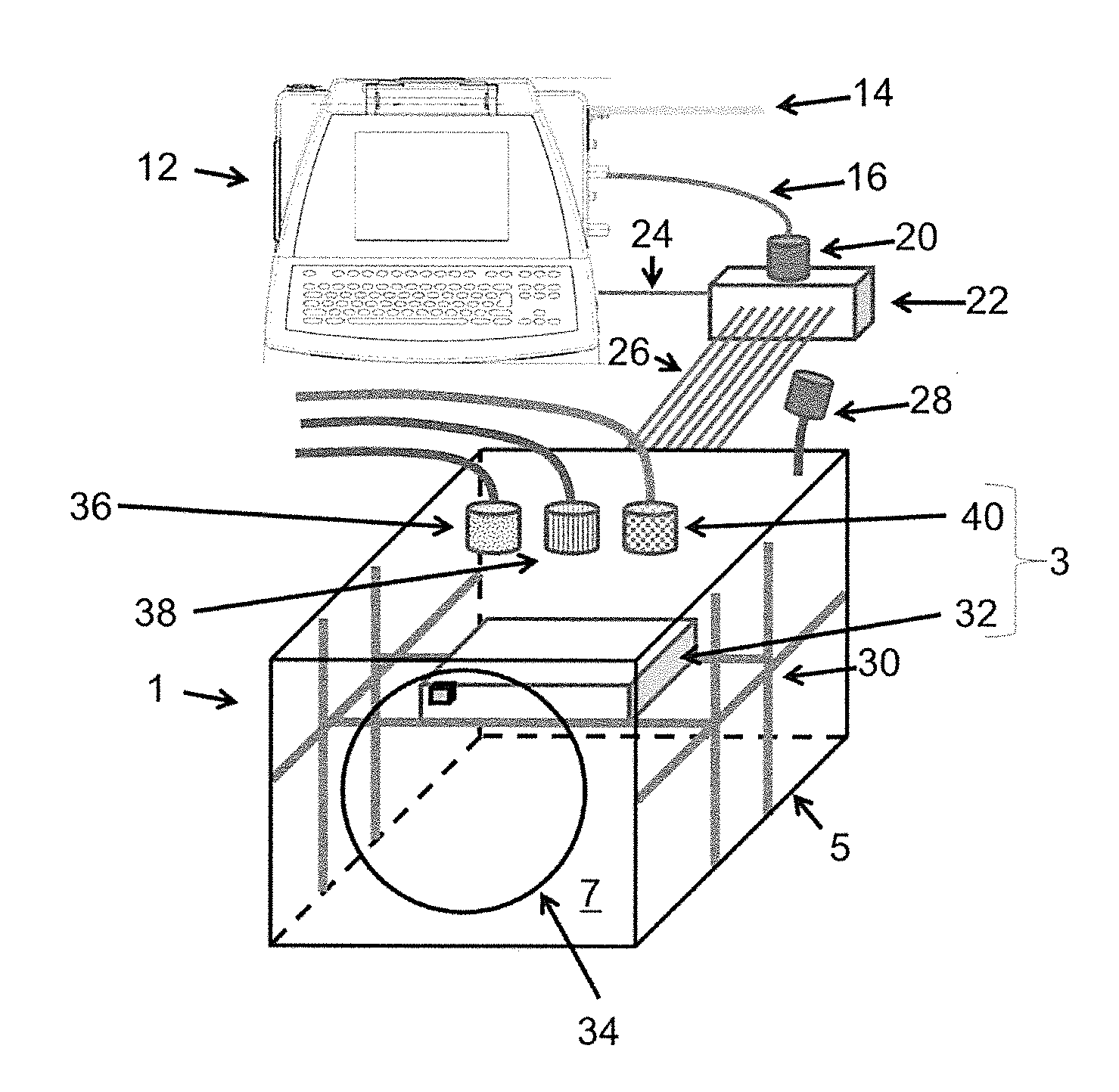
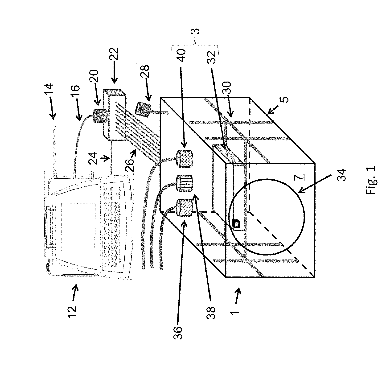
[0128]FIG. 1 shows a three-dimensional printing device 1 comprising a printer housing 5 enclosing a printer assembly 3. The inside of the printer housing 5, particularly the printer assembly 3, is sterilizable and disposable, i.e. intended for single use. The printer housing 5 can be formed of rigid walls or flexible walls 7 held open by a rigid internal and / or external skeleton.

[0129]The three-dimensional printing device 1, particularly the printer assembly 3 and / or the inside of the printer housing 5, can be sterilized by gamma-irradiation, autoclaving, or chemical sterilant (such as ethylene oxide or vaporized hydrogen peroxide). The electronic and controlling components for controlling the printer assembly 3 that are reused or that are sensitive to the sterilization method can be arranged outside the printer housing 5 and might be removably attached to the sterilized three-dimensional printer 1 during setup.

[0130]The at least one printing head of the three-dimensional printing d...


PUM

PropertyMeasurementUnit
movementsaaaaaaaaaa
displacementaaaaaaaaaa
degrees of freedomaaaaaaaaaa

Abstract

A manufacturing assembly has at least a sterilizable chamber containing at least one of a three-dimensional printing device (additive manufacturing), a Computer Numerical Controlled (CNC) finishing head (subtractive manufacturing), a vacuum-forming unit, an injection-molding unit, a laser-cutting unit, a ultrasonic-welding unit, a robotic arman analysis device, a sampling device or a combination thereof. A plurality of individual sterilizable chambers may be aseptically connected into a network of sterilizable chambers that provides additional functionality for the manufacturing assembly. A sterilizable printer assembly may include at least one printing head, a printing platform, and a driving mechanism adapted to perform a movement of the at least one printing head relative to the printing platform along three degrees of freedom; a printer housing enclosing the printer assembly in a sterile manner, at least one aseptic connector fluidly connected to a corresponding one of the at least one printing head.

Description

BACKGROUND[0001]1. Field of the Invention[0002]The invention relates to manufacturing methods for use inside of a sterile / sterilizable single-use three-dimensional container or chamber, manipulation of the manufactured products, and coating, growing, or integrating biologically active materials with those manufactured products.[0003]2. Description of the Related Art[0004]The forming of three-dimensional objects or the coating of three-dimensional objects under sterile conditions, particularly a coating with biochemical materials, requires high effort to uphold the sterile conditions and to assemble the required apparatuses for forming or coating under sterile conditions.[0005]Thus, it is a problem to provide a manufacturing device, a manufacturing system and manufacturing methods that are capable to form, cut, print, or coat a material under sterile conditions in a reliable and easy manner.SUMMARY OF THE INVENTION[0006]The manufacturing operations performed in the systems and / or dev...

Claims


Application Information

Patent Timeline
Patent Type & Authority Applications(United States)
IPC IPC(8): C12M3/00B25J9/10B25J9/14B25J21/00C12M1/00C12M1/12C12M1/34C12M1/36
CPCC12M21/08C12M41/48C12M29/00C12M25/00C12M41/12C12M41/40B33Y80/00B25J9/14B25J21/00Y10S901/19Y10S901/22B33Y30/00B33Y40/00B25J9/10B29C64/112B29C64/255B29C64/209B29C64/188C12M33/00B29C66/0018B29C65/08B29C66/8322B29C66/1122B29C66/43B29C66/73921B29C64/227B29C64/232B29C64/236B29C64/321B29C64/25B29C64/364B29C64/379B29C64/307B29C64/205
Inventor MAGGIORE, FRANK
Owner SARTORIUS STEDIM BIOTECH GMBH
Learn More