Heat Sink Having a Cooling Structure with Decreasing Structure Density

a cooling structure and cooling structure technology, applied in the field of heat sinks, can solve the problems of increasing the cost of heat sinks, preventing the fabrication of more complex heatsink designs, and requiring more complex structures to improve the performance of heat sinks, so as to increase the distance to said center axis.

Inactive Publication Date: 2016-03-10
ALEXIOU & TRYDE HLDG APS
View PDF5 Cites 56 Cited by
  • Summary
  • Abstract
  • Description
  • Claims
  • Application Information

AI Technical Summary

Benefits of technology

[0016]It is within an embodiment of the invention that when defining a center line or axis being substantially perpendicular to the first surface of the body part and going through the center of the body part, the material density of the cooling structure or at least part of the cooling structure decreases with increasing distance to said center axis. Thus, when defining a center line or axis bein

Problems solved by technology

Although these technologies add relatively little cost, they preclude the fabrication of more complex

Method used


Image

  • Heat Sink Having a Cooling Structure with Decreasing Structure Density
  • Heat Sink Having a Cooling Structure with Decreasing Structure Density
  • Heat Sink Having a Cooling Structure with Decreasing Structure Density

Examples


Embodiment Construction

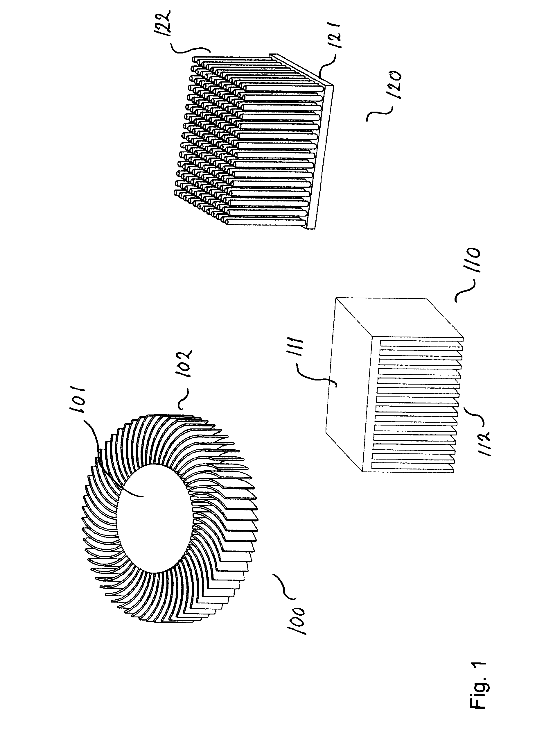
[0059]FIG. 1 illustrates three prior art heat sinks 100, 110, and 120. The first heat sink 100 has a base or core 101 and curved cooling fins 102 connected to the core 101. The fins 102 all have the same curve, and the material thickness of the fins 102 is equal all the way. The heat sink 110 also has a base or core 111 and straight formed fins 112 connected to the core 111, with the material thickness of the fins 112 being equal all the way along the fins 112. The heat sink 120 also has a base or core 121 and pin formed fins 122 connected to the core 121, with the material thickness of the fins 122 being equal all the way along the fins 122. The heat sinks 100, 110, and 120 are representative of the class of heat sinks formed by conventional methods including extrusion, machining and die-casting.

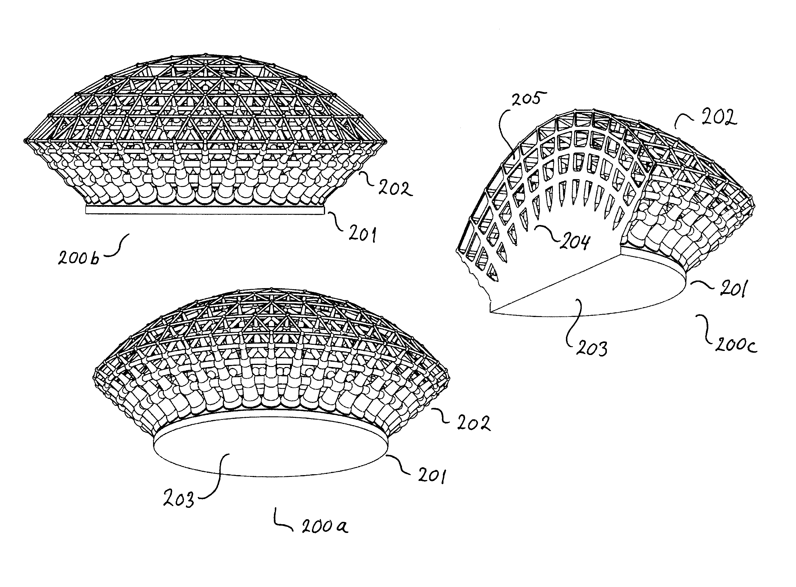
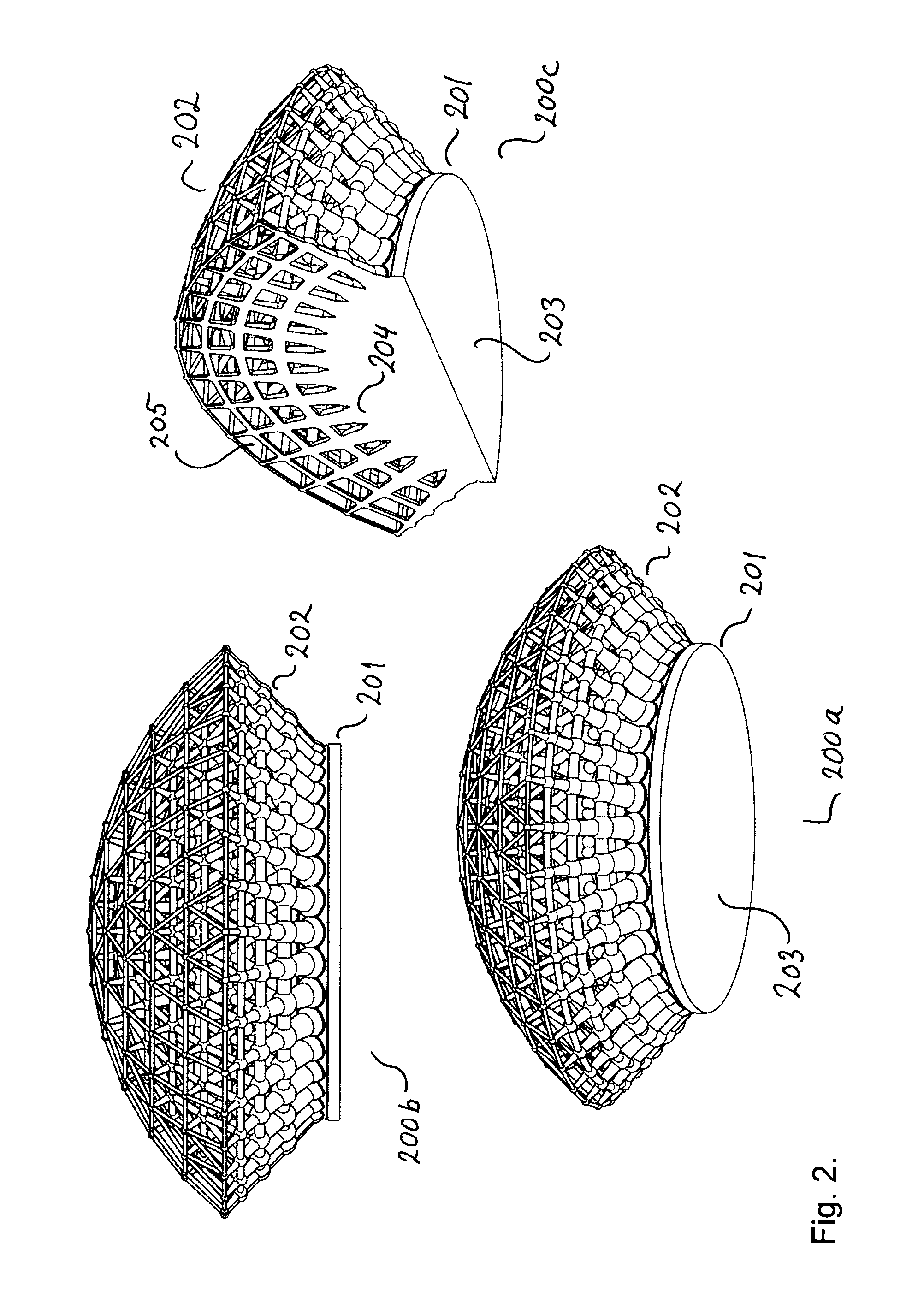
[0060]FIG. 2 illustrates a first embodiment of a heat sink 200 according to the present invention, which heat sink 200 may be formed using a 3-D printing and casting process, such as the se...


PUM

PropertyMeasurementUnit
Diameteraaaaaaaaaa
Thicknessaaaaaaaaaa
Structureaaaaaaaaaa

Abstract

A heat sink for cooling a heat generating device comprises a body part with a first surface for contacting the heat generating device, and a second surface contacting a cooling part, and the cooling part including a cooling structure. The structure density of the cooling structure decreases with increasing distance to body part. The cooling structure may be a three dimensional structure e.g. a grid or a lattice, but the cooling structure may also be fins projecting or extending from the second surface of the body part. The heat sink can be manufactured using additive manufacturing e.g. selective laser melting process (SLM). The heat sink can be made of metals e.g. aluminum, copper, ceramics e.g. aluminium nitride (AlN), silicon carbide or a composite containing graphite, graphene or carbon nanotubes.

Description

FIELD OF THE INVENTION[0001]The present invention relates generally to heat sinks, and more particularly to heat sinks comprising a cooling structure with an outwards decreasing material density. The heat sinks of the present invention may for example be used for dissipating heat generated by electrical or electronic components and assemblies.BACKGROUND OF THE INVENTION[0002]With the rapid rise in power dissipated by integrated circuits, improved heat sink designs are needed to decrease the thermal resistance between them and forced air streams. Manufacturing methods such as extrusion, machining and die-casting have been used to fabricate conventional longitudinal fin designs. Although these technologies add relatively little cost, they preclude the fabrication of more complex heatsink designs. But more complex structures may be needed to improve the performance of heat sinks.[0003]Heat sinks of a more complex structure are described by Hernon et al. in US Patent App. No 2009 / 032104...

Claims


Application Information

Patent Timeline
IPC IPC(8): F28F13/00B23K26/342B23P15/26F28F13/08F28F13/14
CPCF28F13/003B23P15/26F28F13/14F28F13/08B23K26/342H01L23/367H01L23/3675H01L23/3677H01L2924/0002F28F2215/10F21V29/81F21V29/83G06F1/1656G06F1/1681G06F1/203H01L23/473F28F1/40F28F3/02F28F3/022F28F2215/04B22F5/10F21V21/28F21V21/30B33Y10/00F21V29/74F21Y2115/10H01L21/4871Y02P10/25B22F10/28H01L2924/00
Inventor ALEXIOU, ALEXANDRATRYDE, JACOB WILLER
Owner ALEXIOU & TRYDE HLDG APS
Why Eureka
Try Eureka