
Thermal well for transformer and methods

a transformer and thermal well technology, applied in the field of temperature monitoring in transformers, can solve problems such as eventual voltage breakdown and insulation erosion

Active Publication Date: 2016-03-10
ROCKWELL AUTOMATION TECH
View PDF15 Cites 4 Cited by
  • Summary
  • Abstract
  • Description
  • Claims
  • Application Information

AI Technical Summary

Benefits of technology

The present patent is about a thermal well with a sensor that monitors the temperature of an apparatus and stops it from operating when it reaches a predetermined threshold temperature. The thermal well has potting layers to remove air voids, which can cause voltage stress and lead to insulation erosion and voltage breakdown. This helps prevent damage to the insulation and ensures the safe operation of the apparatus.

Problems solved by technology

Continuous operation with corona discharges in the air void can lead to insulation erosion and eventual voltage breakdown well before expected insulation end of life.

Method used


Image

  • Thermal well for transformer and methods
  • Thermal well for transformer and methods
  • Thermal well for transformer and methods

Examples


Embodiment Construction

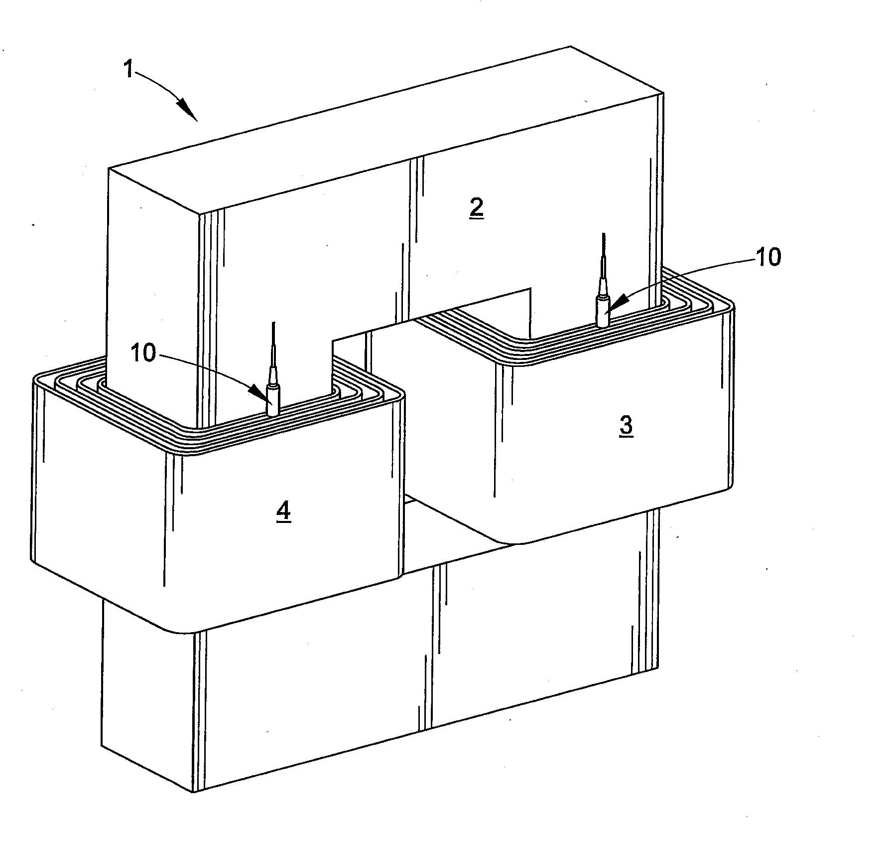
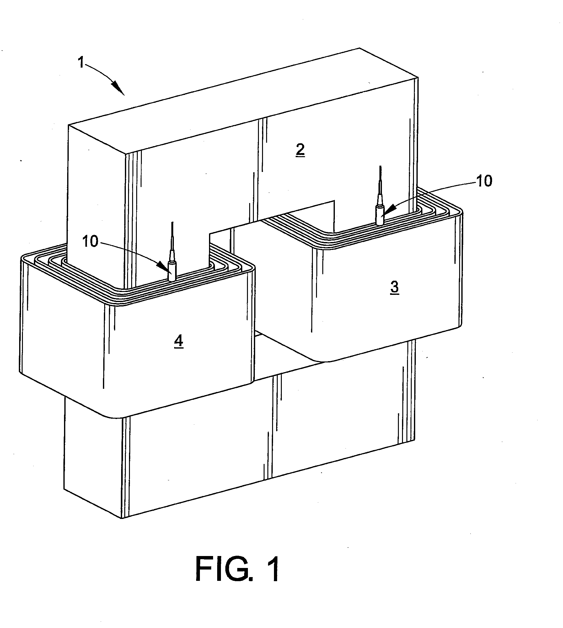
[0013]Various embodiments are hereinafter illustrated and described, wherein the disclosure is not limited to the specific examples shown and described. A temperature monitoring apparatus or thermal well and methods are presented in which a thermal well includes a thermal sensor and one or more low relative dielectric constant potting layers within a low relative dielectric constant structure to mitigate or avoid air gaps in the thermal well. The low dielectric constant structure and potting layers in certain embodiments advantageously mitigate the potential for arcing and build-up of undesirable corona once positioned between high potential transformer coils or windings or in other high voltage or explosive environments.

[0014]Transformers are used for power generation and distribution, often for high energy applications (e.g., oil drilling, natural gas drilling, electricity generation, motor drives, and the like). In use, the transformer primary and secondary coils conduct current ...


PUM


Abstract

A thermal well temperature monitoring assembly with high dielectric strength capability is disclosed consisting of a low relative dielectric constant material in a continuous structure that does not have any air voids or pockets. The low relative dielectric constant structure of the thermal well has at least one internal cavity having an end region. A thermal sensor is at least partially located within the at least one internal cavity. The thermal sensor has one or more wires extending out of the end region of the internal cavity. A first low relative dielectric constant potting material encapsulates at least a portion of the thermal sensor within the internal cavity to remove air voids that decrease dielectric strength. A second low relative dielectric constant potting material fills at least a portion of the end region of the internal cavity to provide mechanical ruggedness and environmental sealing.

Description

CROSS-REFERENCE TO RELATED APPLICATIONS[0001]The instant application claims priority to U.S. Provisional Application Ser. No. 62 / 048,436, filed Sep. 10, 2014, the subject matter of which is incorporated herein by reference in its entirety.BACKGROUND[0002]The subject matter disclosed herein relates to temperature monitoring, and more specifically to temperature monitoring in transformers, especially those containing high voltage windings.BRIEF DESCRIPTION[0003]Various aspects of the present disclosure are now summarized to facilitate a basic understanding of the disclosure, wherein this summary is not an extensive overview of the disclosure, and is intended neither to identify certain elements of the disclosure, nor to delineate the scope thereof. Rather, the primary purpose of this summary is to present various concepts of the disclosure in a simplified form prior to the more detailed description that is presented hereinafter. The present disclosure provides a thermal well with a th...

Claims


Application Information

Patent Timeline
IPC IPC(8): G01K7/00G01K1/08G01K13/00H01F27/40
CPCG01K7/00G01K13/00H01F2027/406H01F27/402G01K1/08
Inventor ANNIS, JEFFREY R.SKIBINSKI, GARY L.
Owner ROCKWELL AUTOMATION TECH
Learn More