Voltage sensing unit for sensing voltage of high-power lines using a single-contact point and method of use thereof

a voltage sensing unit and high-power line technology, applied in the direction of electrical testing, instruments, base element modifications, etc., can solve the problems of de-energized or “knocking out” a line, the electric grid is evolving into a highly sophisticated and complex network, and the independent monitoring of transmission or distribution lines is limited, so as to improve the safety of deploying the sensor, accurate measurement of voltage, and easy deployment

Inactive Publication Date: 2016-03-10
AWESENSE WIRELESS
View PDF2 Cites 18 Cited by
  • Summary
  • Abstract
  • Description
  • Claims
  • Application Information

AI Technical Summary

Benefits of technology

[0033]An elegant and simple method is provided herein to accurately measure voltage using a single contact to one conductor. The sensor comprises a sensing plate which couples to the second conductor through Cg. The sensor is guarded by a shield. Enclosed within this shield is a bank of calibrated capacitors which can be switched in to change the capacitor divide ratio. Using a calibrated and shielded capacitor bank provides a way to make accurate voltage measurements without knowing any of the physical parameters in the system such as conductor spacing and the distance to earth ground. The voltage sensor also is easily deployable in any field situation. The single contact improves the safety of deploying the sensor and avoids making contact between two conductors which is required in other voltage measurement methods.

Problems solved by technology

Most monitoring in the electric distribution grid is done at generation nodes and at large loads, while independent monitoring on transmission or distribution lines has been limited.
However, the electric grid is evolving into a highly sophisticated and complex network as smaller generation nodes are added to the grid.
Thus, high winds, falling trees or other forces occurring during storms or natural disasters may de-energize or “knock out” a line.
The CVT devices are expensive devices directly connected to power lines.
On the other hand, voltage, also called potential, is much more difficult to measure on a single conductor because potential has to be reference to a second conductor.
Standard voltage measurements require two points of contact across two conductors making this kind of measurement dangerous at high voltages.
These low-voltage sensors also have a poor response to voltage transients when over-saturated and have limited use.
There is also the issue of accuracy: low cost sensors detect whether there is a voltage or not and provide an estimate of the voltage only.

Method used


Image

  • Voltage sensing unit for sensing voltage of high-power lines using a single-contact point and method of use thereof
  • Voltage sensing unit for sensing voltage of high-power lines using a single-contact point and method of use thereof
  • Voltage sensing unit for sensing voltage of high-power lines using a single-contact point and method of use thereof

Examples


example 1

Measuring Voltage

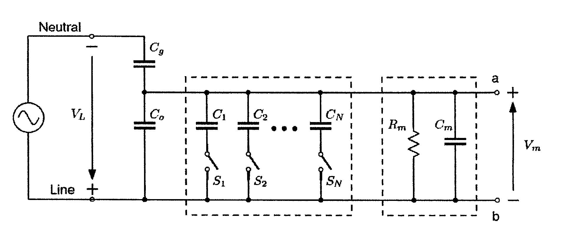
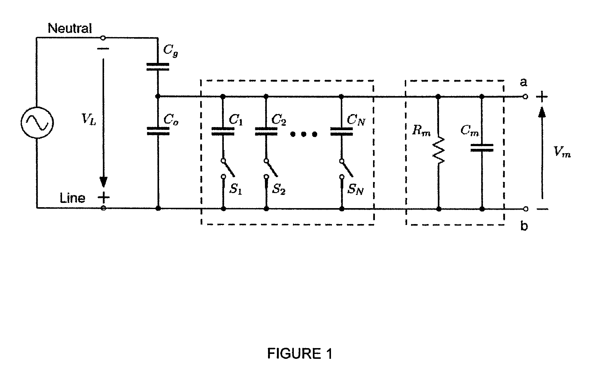
[0178]The sensor voltage is measured across the external capacitance between nodes A and B. The voltage is buffered by a high-input impedance voltage follower using an Intersil CA3140 op-amp. The op-amp uses two nine volt batteries providing supply voltages of + / −9 V where the common mode voltage is referenced to the line voltage (hot conductor). The output of the buffer is connected to an Agilent DVM model 34401A which is used to record the sensor voltage. Since the DVM loads the sensor, the measurement model preferably includes compensation for Rm and Cm, the effective input resistance and capacitance of the meter. For this example, Rm is 10 Mohm and Cm is 370 pF. The DVM has analog to digital converters (ADC's) which are floating relative to the potential of the high voltage line. The maximum differential voltage between the input of the meter and ground (neutral) is rated for 500 VAC. This limitation can be removed using an optocoupler.

[0179]Three silver mica 13...

example 2

Linearity Test

[0180]To check the linearity of the measured sensing voltages, a figure is plotted based on input voltages versus sensing voltages. This is shown graphically in FIG. 8. From this figure, it is clear that the sensing voltages, V1, V2 and V3 are linear.

example 3

Factory Calibration to Estimate the Unknown Capacitances

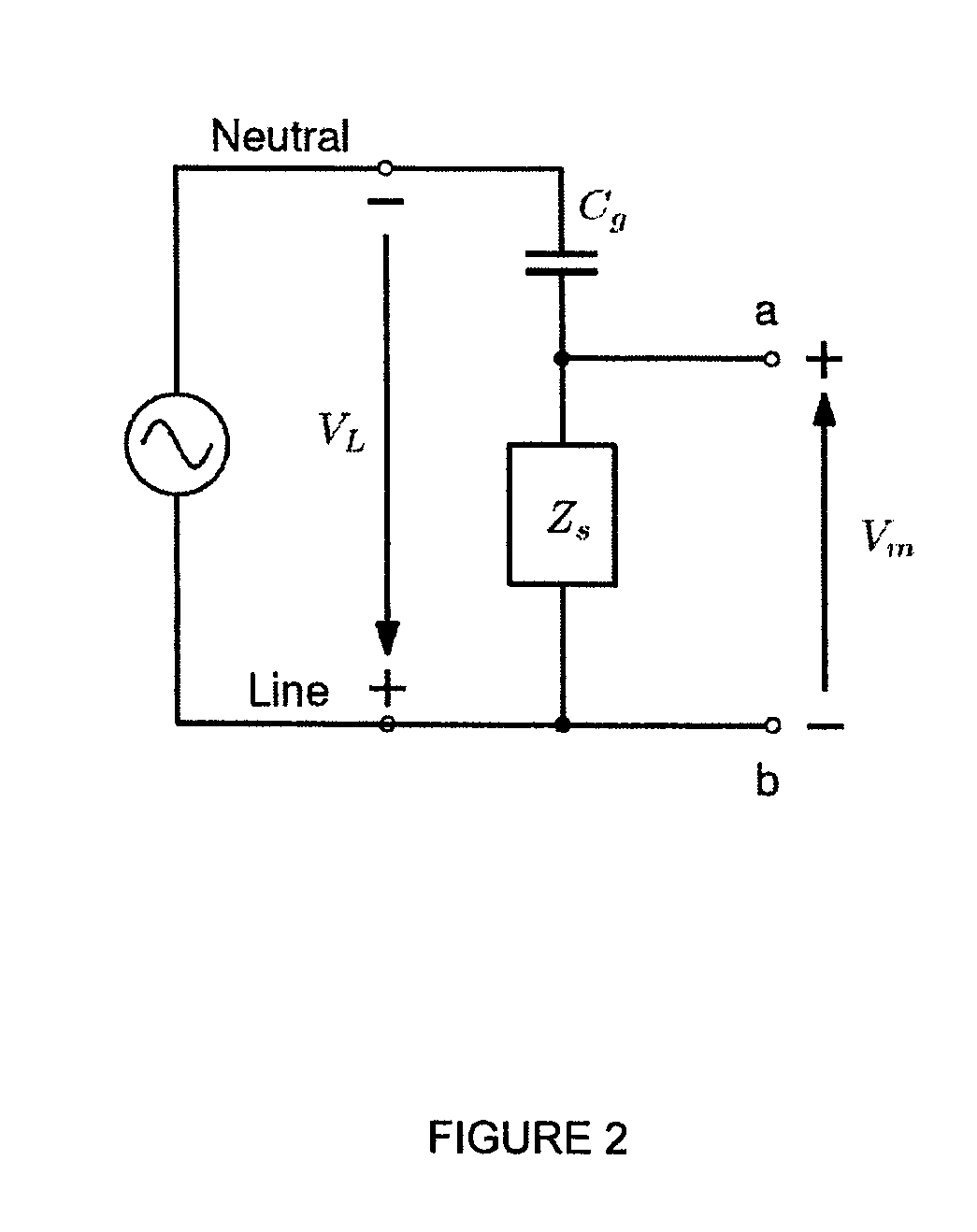
[0181]A numerical method is developed to solve for the unknown values (Co, Cg, and VL) by applying three parallel capacitances successively across the voltage sensor on the high-voltage line. This numerical method has been implemented in Matlab code to validate the measurement method. If the first capacitance C1 is connected across Co, then the voltage V1 from node A to node B can be calculated from the following equation: It is to be noted that the high impedance buffer removes the contribution of Cm and the input capacitance of the buffer, from hereon, is assumed to be absorbed in the value of Co.

V1=VLCgCg+C0+C.(1)

[0182]Similarly, if the second and third capacitances are connected, the corresponding voltages V2 and V3 are:

V2=VinCgCg+C0+2C(2)V3=VinCgCg+C0+3C(3)V2=VLCgCg+C0+2CV3=VLCgCg+C0+3C.V2=VLCgCg+C0+2C(2)V3=VLCgCg+C0+3C.(3)

[0183]By simplifying equation 1 to 3 the following is attained:

V1Cg−VinCg+V1Co+V1C0  (4)

V2Cg−VinCg+V2...


PUM


Abstract

A method is provided of ascertaining an unknown line (conductor) voltage at point X on a power line within an electrical grid comprises collecting raw voltage at or about Point X using a sensor; gathering additional data from data collection sources upstream (comprising, for example a substation) and/or downstream (comprising, for example, smart meters) to Point X (constraining data); using raw voltage, and environment and line data (comprising at least one of GPS location of sensor, GIS data of the electrical grid, phase, type of conductor, total load on conductor), to calculate voltage range at Point X; and using constraining data sequentially to bind (narrow and tighten) the voltage range from a determined range of possibilities to a likely absolute voltage measurement.

Description

FIELD OF THE INVENTION[0001]The present invention to the field of power monitoring and devices to achieve such means within a power grid.BACKGROUND OF THE INVENTION[0002]In the generation, transmission, and distribution of electric power it is important to monitor line voltage, line current, and the phase between voltage and current (power factor). Most monitoring in the electric distribution grid is done at generation nodes and at large loads, while independent monitoring on transmission or distribution lines has been limited. However, the electric grid is evolving into a highly sophisticated and complex network as smaller generation nodes are added to the grid. The term ‘smart grid’ is now used to capture the sophisticated monitoring and control that is being deployed to improve the efficiency and stability of the grid.[0003]Electrical utilities need to monitor their power lines to determine when lines are down or in need of repair, and when power transmission to specific areas ne...

Claims


Application Information

Patent Timeline
Patent Type & Authority Applications(United States)
IPC IPC(8): G01R19/00G01R15/16
CPCG01R15/16G01R19/0084G01R29/12G01R35/005G01R21/006G01R21/06
Inventor JOHNSON, THOMAS EDWARDBOBOWSKI, JAKE STANLEYSLAMKA, RICK
Owner AWESENSE WIRELESS
Why Eureka
Try Eureka