System and Method for Explicit Model Predictive Control

a model and model technology, applied in adaptive control, process and machine control, instruments, etc., can solve problems such as challenging tasks, system operation, and mpc solving nonlinear programs in real-time, and achieve the effect of reducing processing time and high degree of atomicity

Active Publication Date: 2016-03-10
MITSUBISHI ELECTRIC RES LAB INC
View PDF7 Cites 6 Cited by
  • Summary
  • Abstract
  • Description
  • Claims
  • Application Information

AI Technical Summary

Benefits of technology

[0009]Some embodiments of the invention are based on a realization that an explicit model predictive control (EMPC) largely includes basic operations performed repeatedly. These operations also exhibit a very high degree of atomicity, meaning that they do not share information, and thus can be performed in parallel to reduce processing time.

Problems solved by technology

Nonlinear MPC solves nonlinear programs in real-time, which can be a challenging task due to limited computing resources, the complexity of the problem to solve, or the time available to solve the problem.
For example, the constraints can represent physical limitations of the system, legitimate and safety limitations on the operation of the system, and performance limitations on a trajectory.
However, the MPC is computationally expensive because it requires that an optimization problem be solved at each time step in order to calculate the control output of the system.
However, the real-time part of the EMPC may still require many thousands operations for searching the state space, which makes explicit model predictive controllers implemented using general purpose computing units and circuitry too slow for some real-time control applications, especially when the MPC optimal control problem has many decision variables and / or constraints.
In contrast with the general purpose circuitry, it is always a challenge to optimize the design of the application-specific circuits for the specific problem.

Method used


Image

  • System and Method for Explicit Model Predictive Control
  • System and Method for Explicit Model Predictive Control
  • System and Method for Explicit Model Predictive Control

Examples


Embodiment Construction

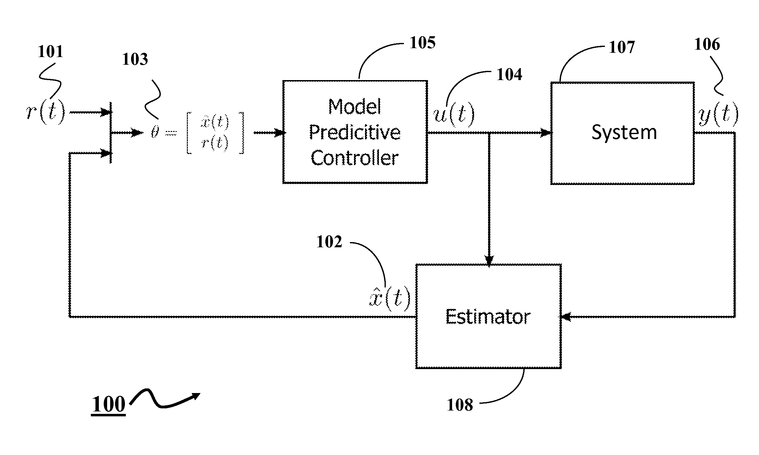
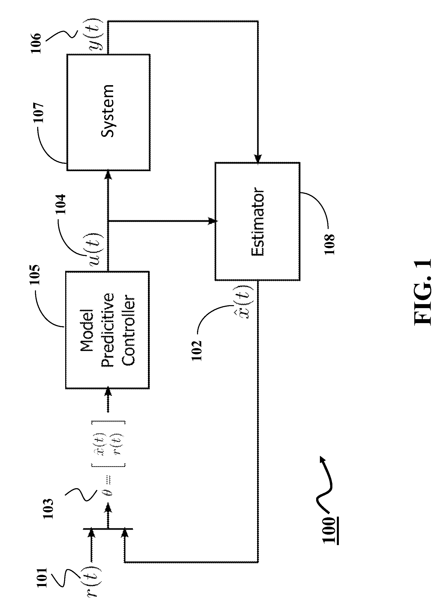
[0029]FIG. 1 shows a block diagram of a control system 100 using an explicit model predictive control (EMPC) according to some embodiments of the invention. The control system 100 includes a model predictive controller 105 and a state estimator 108 to control a system 107. During the operation, the controller receives a reference signal r(t) 101 indicating the reference operation of the system as a function of time t. The reference signal can be, for example, a motion or a position command, or represent the desired value of some parameter in the system. In response to receiving the reference signal r(t) 101, the controller generates a control signal u(t) 104 for the system. In response to the input, the system updates the output y(t) 106 and the state x(t) 102 of the system.

[0030]The system can be any device that is controlled by manipulating control signals (inputs), possibly associated with physical quantities such as voltages, pressures, forces, and returns system output possibly...


PUM


Abstract

A method for controlling a system using an explicit model predictive control (EMPC) evaluates, with respect to a state of the system, each inequality in a set of inequalities defining a set of regions of a state space of the system to produce a set of Boolean results. At least some of the inequalities are evaluated concurrently, and a size of the set of Boolean results equals a size of the set of inequalities. The method determines a region including the state by applying a Boolean function to elements of the set of Boolean results corresponding to inequalities forming boundaries of the region and determines a control for the system based on the state and a gain associated with the region. At least some Boolean functions are applied to corresponding elements concurrently after all elements in the set of Boolean results are evaluated.

Description

FIELD OF THE INVENTION[0001]This invention relates generally to controlling an operation of a system, and more particularly to controlling the operation using an explicit model predictive control (EMPC).BACKGROUND OF THE INVENTION[0002]Many advanced control techniques are formulated as optimization problems, which can be solved by programming. One class of such techniques is optimization-based receding time horizon control, such as model predictive control (MPC). There are MPC formulations for both linear and nonlinear systems. Nonlinear MPC solves nonlinear programs in real-time, which can be a challenging task due to limited computing resources, the complexity of the problem to solve, or the time available to solve the problem. Therefore, most of the practical applications are based on a linearity assumption or approximation. The linear MPC typically solves a quadratic programming problem.[0003]The MPC is based on an iterative, finite time horizon optimization of a model of a syst...

Claims


Application Information

Patent Timeline
Patent Type & Authority Applications(United States)
IPC IPC(8): G05B13/04
CPCG05B13/048
Inventor GOLDSMITH, ABRAHAMDI CAIRANO, STEFANO
Owner MITSUBISHI ELECTRIC RES LAB INC
Why Eureka
Try Eureka