Self-powered, ultra-sensitive, flexible tactile sensors based on contact electrification

a tactile sensor and contact electrification technology, applied in the field of touch sensors, can solve the problems of power consumption and structural complexity, deformation dependence poses a challenge, and none of them can normally opera

Active Publication Date: 2016-03-10
GEORGIA TECH RES CORP
View PDF33 Cites 50 Cited by
  • Summary
  • Abstract
  • Description
  • Claims
  • Application Information

AI Technical Summary

Benefits of technology

[0010]The disadvantages of the prior art are overcome by the present invention which, in one aspect, is a tactile sensor for sensing touch from a human finger and the like that includes a triboelectric layer, having a first side and an opposite second side, that includes a material that becomes electrically charged after being in contact with the finger. A first conductive layer has a first side and an opposite second side. The first side of the first conductive layer is in contact with the second side of triboelectric layer. A second conductive layer, has a first side and an opposite second side. A dielectric layer has a first side and an ...

Problems solved by technology

Such a deformation-dependence poses a challenge in touch detection when very weak interaction is involved.
Another major limitation of aforementioned sensors is that they all require an external power supply to generate an electrical parameter for characterizing the output of the sensor; otherwise none of them can normally operate.
This causes problems such as power consumption and structural complexity.
Besides, fragility, stiffness, and high cost are also common concerns that impair widespread adoption of tactile sensors...

Method used


Image

  • Self-powered, ultra-sensitive, flexible tactile sensors based on contact electrification
  • Self-powered, ultra-sensitive, flexible tactile sensors based on contact electrification
  • Self-powered, ultra-sensitive, flexible tactile sensors based on contact electrification

Examples


Embodiment Construction

[0022]A preferred embodiment of the invention is now described in detail. Referring to the drawings, like numbers indicate like parts throughout the views. Unless otherwise specifically indicated in the disclosure that follows, the drawings are not necessarily drawn to scale. As used in the description herein and throughout the claims, the following terms take the meanings explicitly associated herein, unless the context clearly dictates otherwise: the meaning of “a,”“an,” and “the” includes plural reference, the meaning of “in” includes “in” and “on.”

[0023]U.S. patent application Ser. No. 13 / 598,132 , filed on Aug. 29, 2012 by Wang et al. and published as US-2013-0049531-A1 and U.S. patent application Ser. No. 14 / 189,656, filed on Aug. 25, 2014 by Wang et al. and published as US-2014-0246950-A1 each disclose methods of fabricating and operation of triboelectric generators and are therefore incorporated herein by reference.

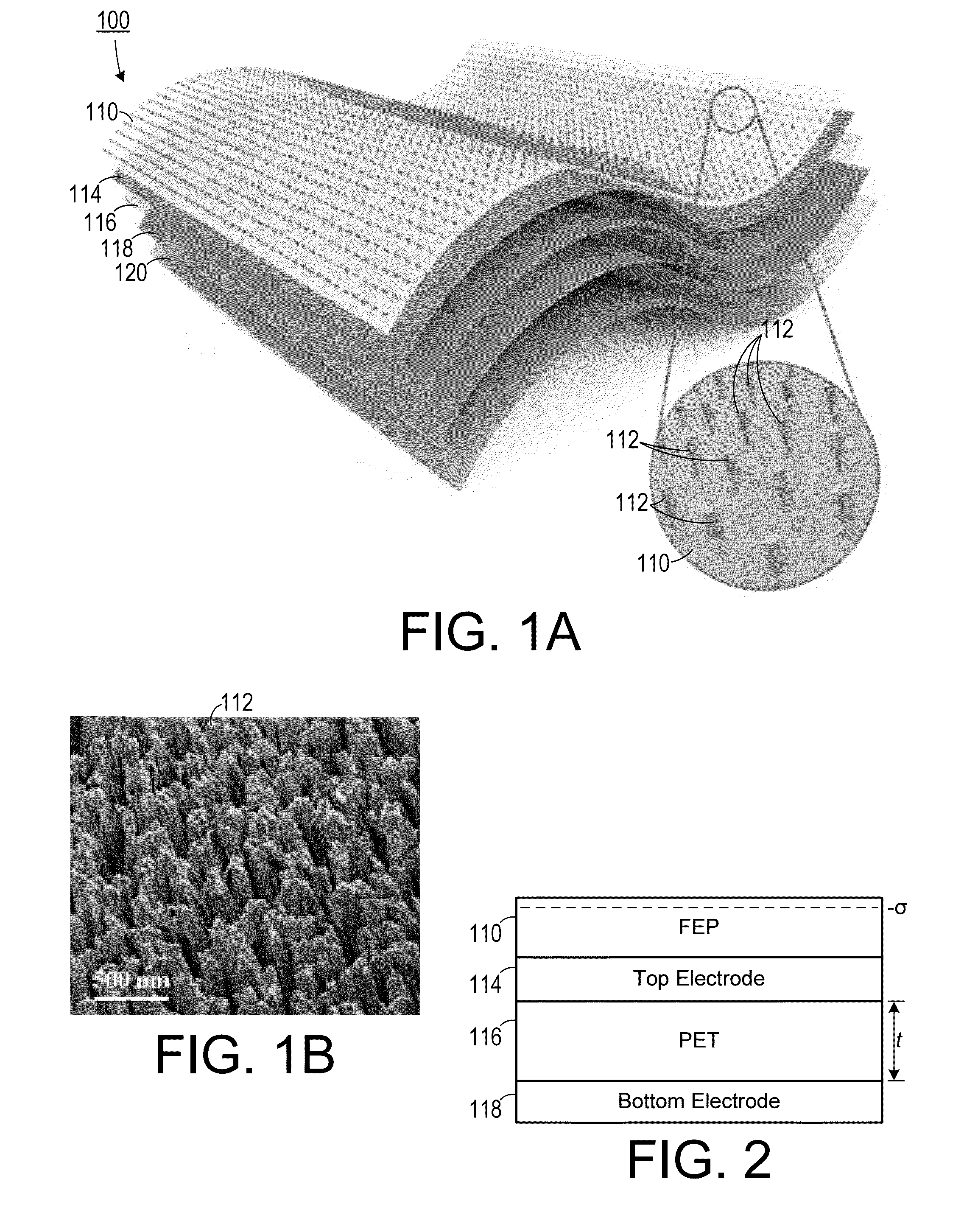
[0024]As shown in FIGS. 1A-1B and FIG. 2, one embodiment...


PUM


Abstract

A tactile sensor for sensing touch from a human finger includes a triboelectric layer and includes a material that becomes electrically charged after being in contact with the finger. The first side of a first conductive layer is in contact with the second side of triboelectric layer. The first side of a dielectric layer is in contact with the first conductive layer and the second side of the dielectric layer is in contact with a second conductive layer. When the triboelectric layer becomes electrically charged after being in contact with the finger, the first conductive layer and the second conductive layer are subjected to an electric field, which has a first field strength at the first conductive layer and a second field strength, different from the first field strength, at the second conductive layer. A plurality of tactile sensors can be arranged as a keyboard.

Description

CROSS-REFERENCE TO RELATED APPLICATIONS[0001]This application claims the benefit of U.S. Provisional Patent Application Ser. No. 62 / 033,384, filed Aug. 5, 2014, the entirety of which is hereby incorporated herein by reference.STATEMENT OF GOVERNMENT INTEREST[0002]This invention was made with government support under agreement No. DE-FG02-07ER46394, awarded by the Department of Energy. The government has certain rights in the invention.BACKGROUND OF THE INVENTION[0003]1. Field of the Invention[0004]The present invention relates to touch sensors and, more specifically, to a touch sensor that is self-powering.[0005]2. Description of the Related Art[0006]Tactile (or touch) sensing is a field that is rapidly advancing as driven by vast applications including human-machine interfacing, skin-like electronics, industrial automation, medical procedures, and security systems. Tactile sensors, according to transducing mechanisms, can be divided into following major categories: capacitive, piez...

Claims


Application Information

Patent Timeline
IPC IPC(8): G06F3/046G06F3/041
CPCG06F3/046G06F2203/04103G06F2203/04102G06F3/0414G06F3/04144H03K17/96H03K17/964H03K17/9643
Inventor WANG, ZHONG LINZHU, GUANG
Owner GEORGIA TECH RES CORP
Why Eureka
Try Eureka