Nail Shaper

Inactive Publication Date: 2016-03-17
RIZZI JOANNE
View PDF8 Cites 2 Cited by
  • Summary
  • Abstract
  • Description
  • Claims
  • Application Information

AI Technical Summary

Benefits of technology

[0010]The present invention provides a method to obtain the desired shape, uniformly for each nail, with a single cut for each nail. It also provides a device which is designed to facilitate ease of cutting the nail; the assembly is especially designed for use by those with reduced strength or coordination.
[0011]The present invention employs at least one pre-shaped set of blades 20, said blades set in a clipping device 10 having a first lever 30, a base 40, and a biasing member 50. The device 10 may be used by placing the base 40 on a surface and then positioning the distal edge 102 of a nail 100 between the p

Problems solved by technology

More importantly, as one nail is shaped, the one shaped just prior may need to be adjusted a bit; these adjustments go on as each of the additional nails are filed and shaped which can be quite time consuming.
For either task, the el

Method used


Image

  • Nail Shaper
  • Nail Shaper
  • Nail Shaper

Examples


Embodiment Construction

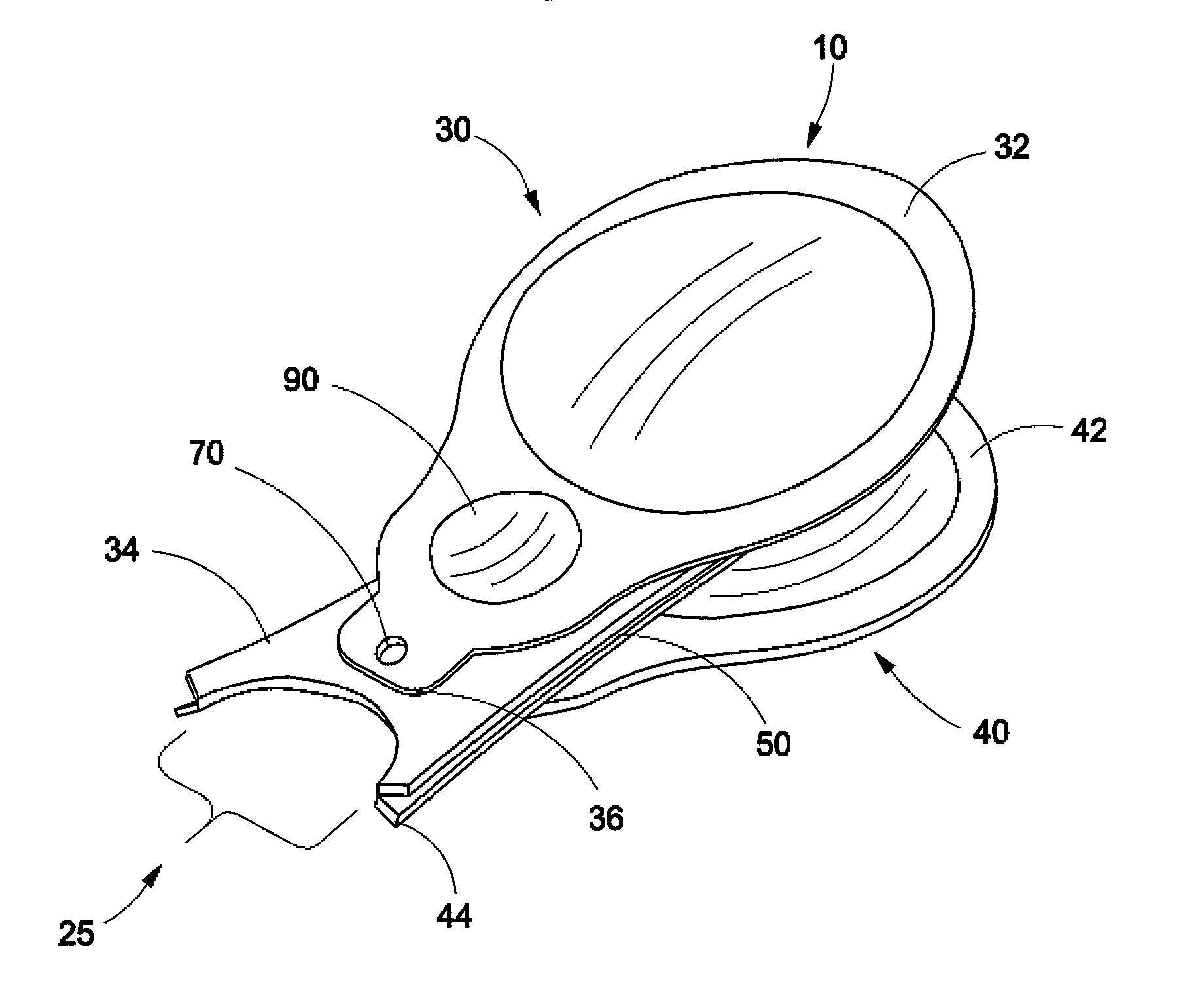
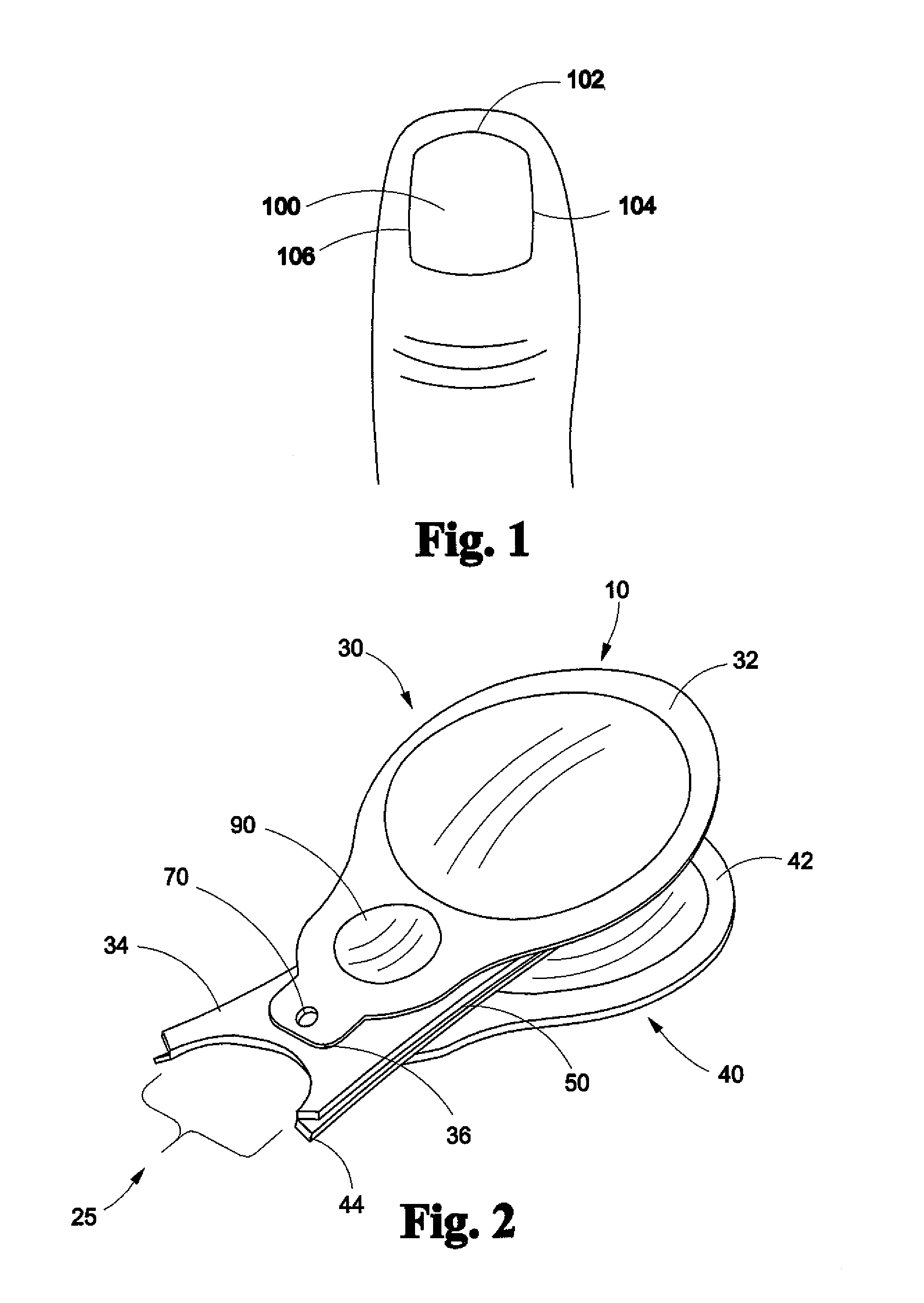
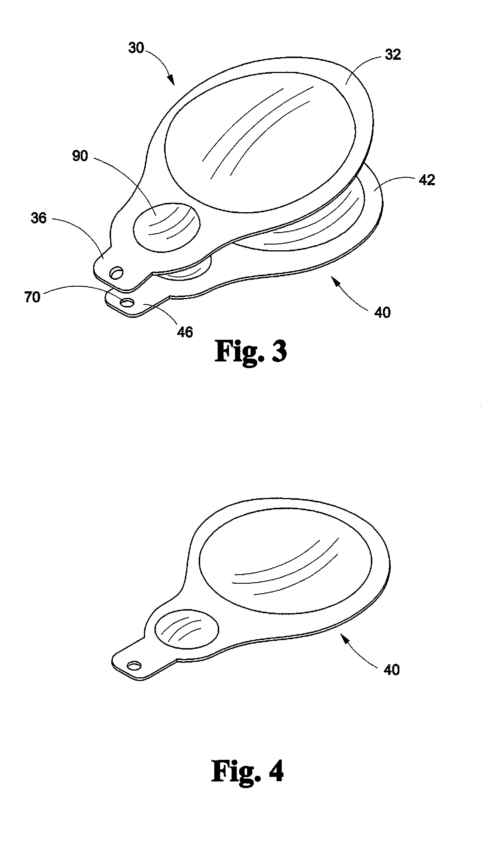
[0020]The present invention provides a device 10 to shape a nail 100 and a method of using the device 10 to achieve a uniform manicure in less time than prior manicuring methods. In one embodiment, the device 10 includes a pair of blades 20a and 20b, a first lever 30 and a base 40 which are separated by a biasing element 50 biasing a first end 32 of the first lever 30 and a first end 42 of the base 40 apart. The biasing element 50 may comprise a metal or plastic spring or springs, a tab or strut-like element made of resilient and compressible material, a resilient biasing member. One of ordinary skill in the art would understand there are many ways to provide resilient bias between two elements which are associated at one end in a spaced apart manner. The blades 20a and 20b each comprise a cutting end, 34 and 44. The cutting ends further comprise a shape 25. The device 10 may comprise integration of a second end 36 of the first lever 30 which may be associated with the blade 20a nea...


PUM


Abstract

A nail clipping device is disclosed which is designed to increase ease of use for users with diminished capacity, improve uniformity, and increase efficiency of a manicure. The device includes a lever and base each associated with a blade; the blades are biased apart and the device includes at least one stand-off to magnify pressure applied to the lever. The base may be designed to rest on a work surface eliminating the need for a user to squeeze the blades together. A cutting end of each blade comprises a shape; in one embodiment the cutting ends are detachable allowing interchangeability for different shapes.

Description

CROSS-REFERENCE TO RELATED APPLICATION[0001]This application claims the benefit of U.S. Provisional Application No. 61 / 993,404 filed with the United States Patent and Trademark Office on May 15, 2014, the entire contents of which is hereby incorporated by referenceFIELD OF INVENTION[0002]The present invention relates, in general, to manicuring tools and, more specifically to a device for shaping a fingernail or toenail.BACKGROUND[0003]For many years, people have been manicuring or having manicured toenails and / or fingernails. The process almost always includes a plurality of steps and iterations comprising, generally, the steps of cutting, shaping and smoothing the nail's edges.[0004]A nail—toe or finger—comprises a nail plate. The nail plate is attached to the body by the nail matrix located under the cuticle and from which the nail grows and by the nail bed which is located between the finger (or toe) and the nail. The portion of the nail plate near the cuticle is the lunula; the ...

Claims


Application Information

Patent Timeline
IPC IPC(8): A45D29/06A45D29/02
CPCA45D29/02A45D29/06
Inventor RIZZI, JOANNE
Owner RIZZI JOANNE
Why Eureka
Try Eureka