Imaging apparatus and positioning apparatus

a positioning apparatus and positioning technology, applied in the field of positioning apparatus, can solve the problems of not allowing direct positioning of sagittal section and coronal section, potential safety risk, harmful to the eyes of the body, etc., and achieve the effect of reducing the workload of pre-positioning imaging sequence and avoiding radiation risk

Inactive Publication Date: 2016-03-17
SIEMENS HEALTHCARE GMBH
View PDF5 Cites 4 Cited by
  • Summary
  • Abstract
  • Description
  • Claims
  • Application Information

AI Technical Summary

Benefits of technology

[0012]An object of the present invention is to provide an imaging device and a positioning apparatus that are capable of reducing pre-positioning imaging sequence workload and avoiding the risk of radiation on the body to be detected.
[0014]In the imaging apparatus of the present invention, which operates according to the inventive method, the target imaging on the patient's body can be recognized in one step and the body can be automatically moved to the isocenter, thus reducing the pre-positioning imaging sequence workload, improving the workflow efficiency, and meanwhile avoiding the errors due to manual positioning by an operator of the imaging device, and thus being particularly effective for an open imaging unit in a current imaging unit, such as a permanent magnet-type magnetic resonance imaging device. Furthermore, in the present invention, the wording “position in at least one direction in space” means a position of distance along any one of an X axis, a Y axis or a Z axis in a spatial coordinate system.
[0015]According to the distance / angle positioning unit in the imaging apparatus of the present invention, the operator of the imaging apparatus can use his knowledge of anatomy and iconography to directly define a center to be imaged in a single operation and at any location on the patient's body, this will help the operator to create the imaging of the patient closer to the diagnostic requirements. The imaging apparatus according to the present invention will save significant preparation time for the operator, thereby increasing the operating efficiency of the imaging device, and improving the health examination capability of a hospital / clinic.
[0016]In addition, the imaging apparatus according to the present invention can transmit a detection signal from the signal generator to a signal receiver provided at the imaging unit. Since the signal radiation path is higher than the patient, there is no risk of radiation on the patient, and thus additional protective apparatuses are unnecessary and the associated costs can be reduced.
[0017]In addition, the imaging apparatus according to the present invention allows positioning in a three-dimensional space, and with the development of imaging devices in the future, the function of positioning in a three-dimensional space will be more helpful. By means of positioning in a three-dimensional space, a coordinate system can be established based on the operator's intention, which will help to further improve the image reconstruction, quality as well as speed.
[0025]The positioning apparatus according to the present invention can provide a direct and accurate position and angle positioning in space.

Problems solved by technology

In the method described above, the MR system allows only direct positioning in the longitudinal direction, i.e. positioning of the transverse section, and does not allow direct positioning of the sagittal section and the coronal section.
Therefore, even if an operator who has knowledge of imaging is clearly aware of which part needs to be scanned, this traditional positioning method cannot transform the operator's intention directly into imaging, and the operator needs to run a special pre-positioning imaging sequence to redefine the transverse section, the sagittal section and the coronal section, so as to determine the final target imaging position, and after that a real imaging examination can be carried out.
In addition, there is a potential safety risk with the laser marker, which is harmful to the eyes of the body to be detected due to the radiation.
This requires additional safety measures and means, and makes the system more complex.
However, as described above, all these methods are only able to achieve longitudinal positioning, and the operator still requires a pre-positioning imaging sequence to obtain a pre-positioning image for determining the final target imaging position.

Method used


Image

  • Imaging apparatus and positioning apparatus
  • Imaging apparatus and positioning apparatus
  • Imaging apparatus and positioning apparatus

Examples


Embodiment Construction

[0039]In the figures, reference characters are as follows:

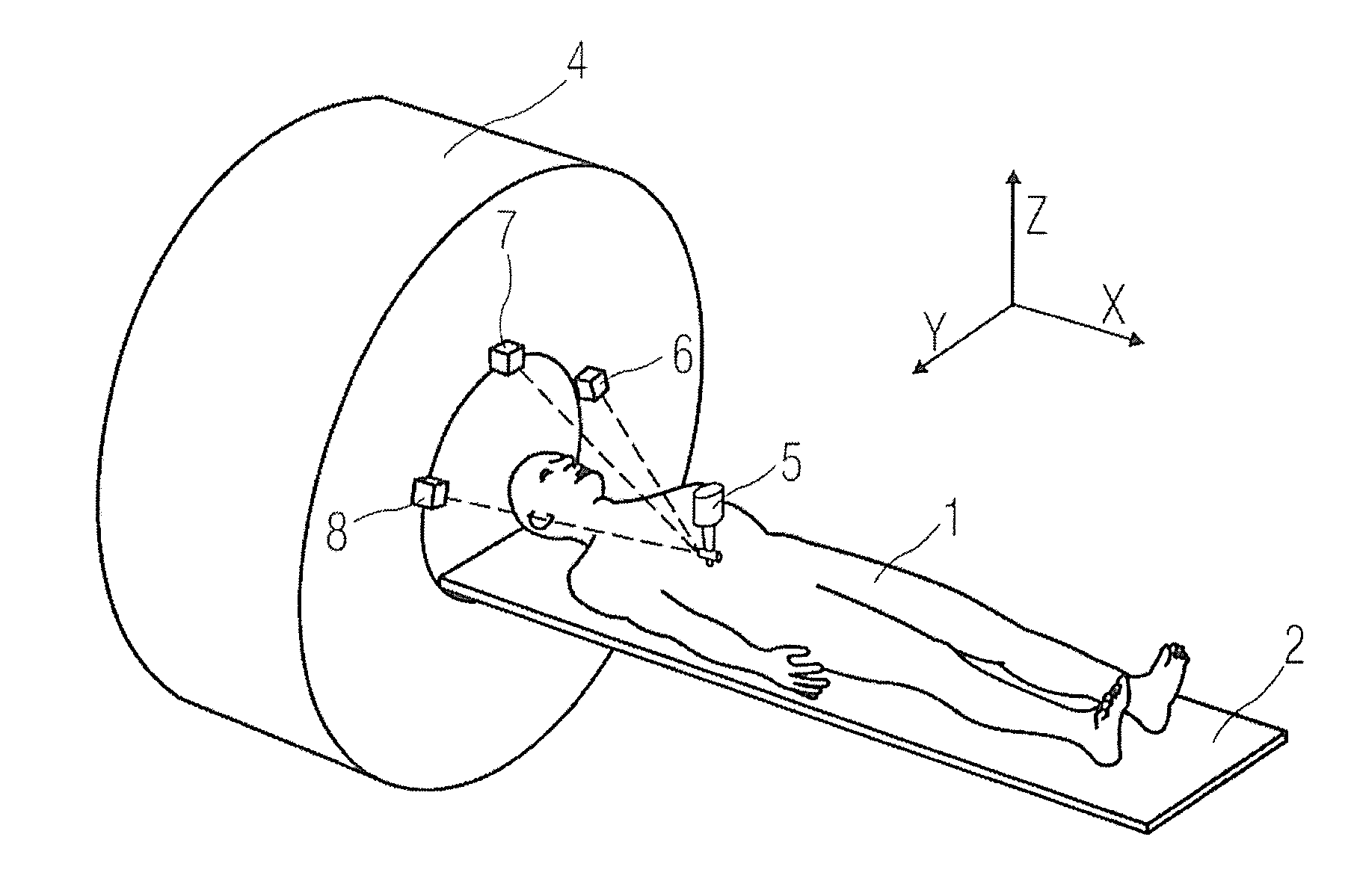
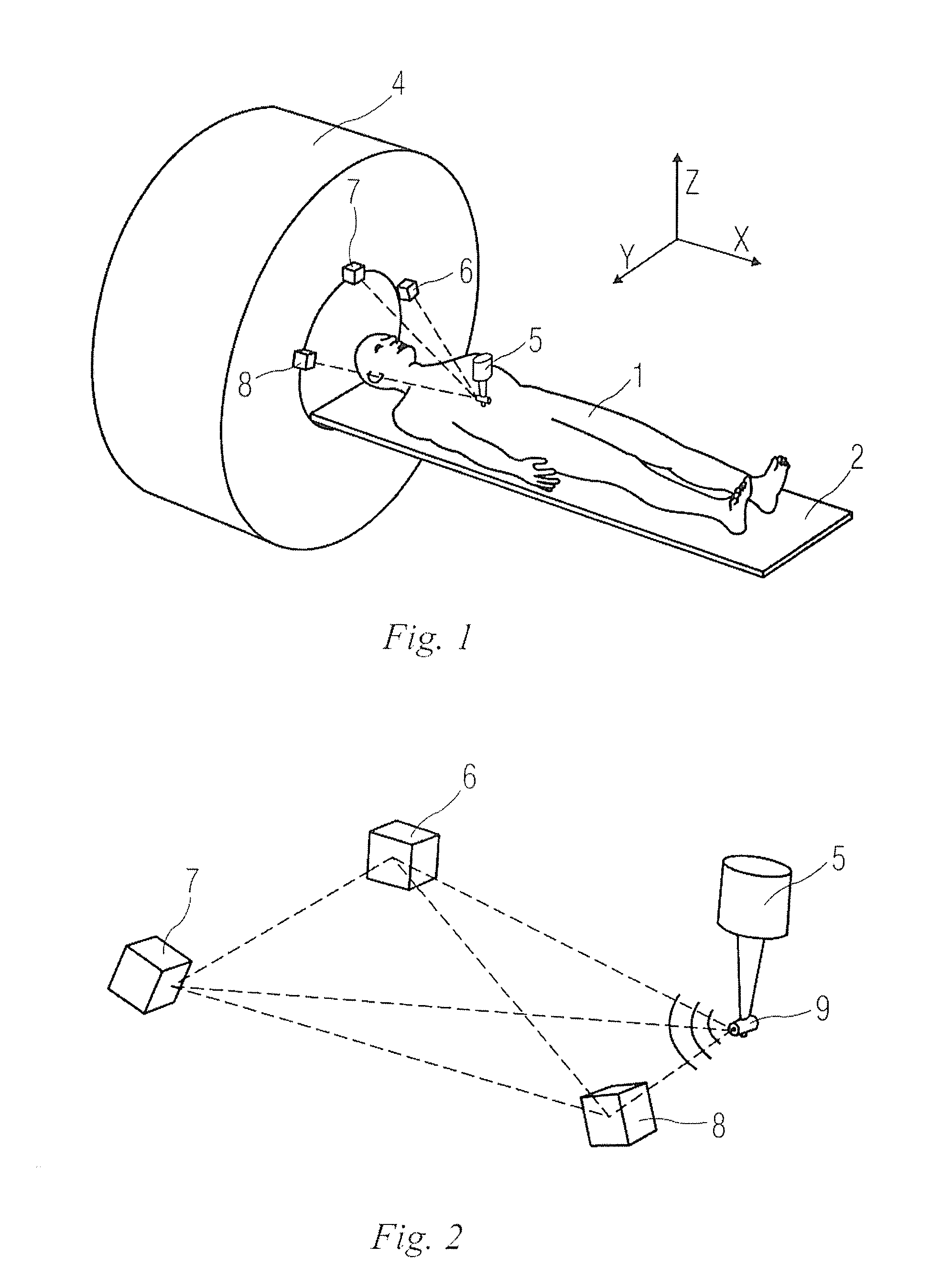
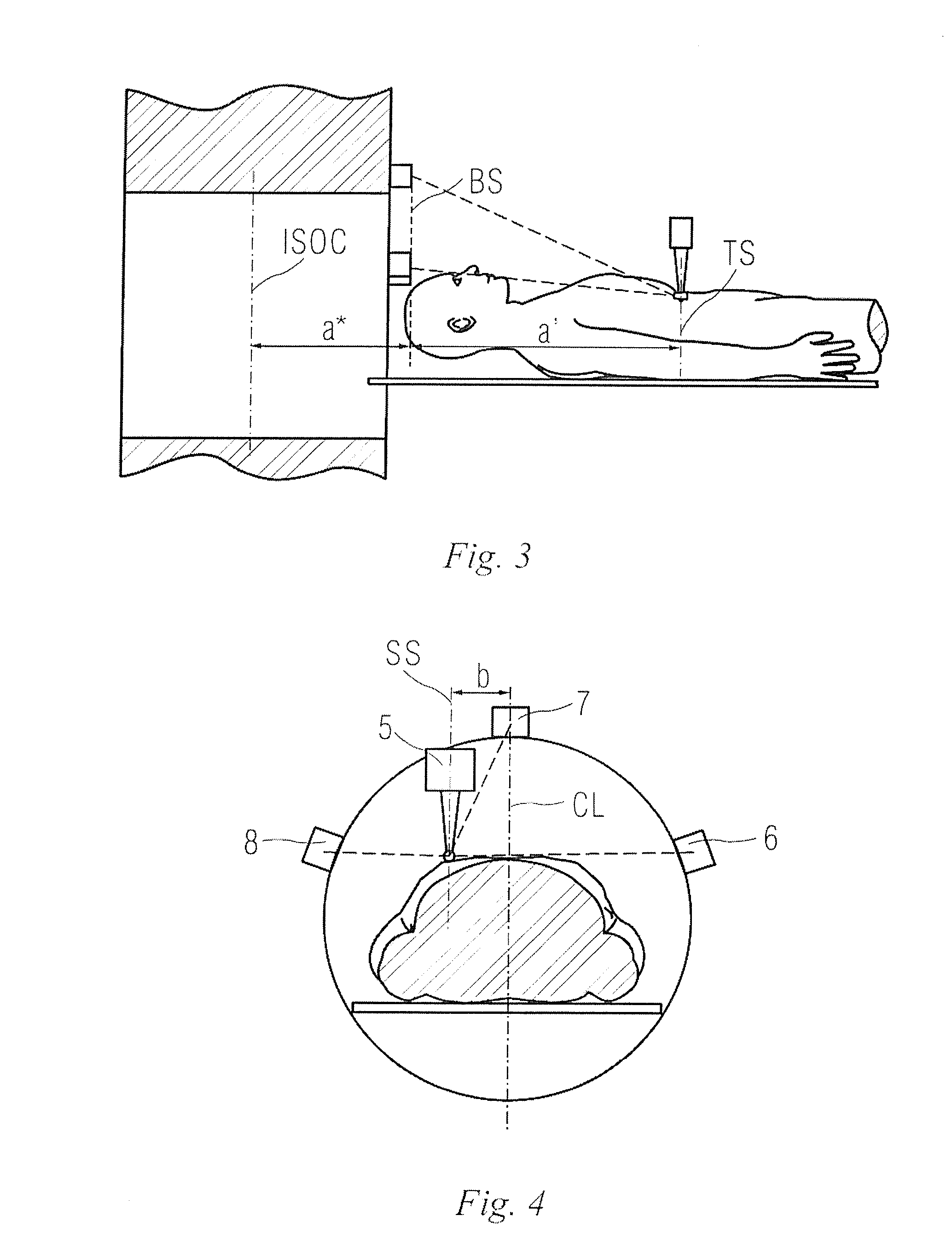
[0040]1 body to be detected; 2 examining bed; 3 detected part; 4 imaging unit; 5 indicator; 6, 7, 8 signal detector; 9 signal generator; 10 handle; 11, 12 angle detector; and 13 auxiliary signal generator.

[0041]FIG. 1 schematically illustrates an imaging apparatus in a first embodiment of the present invention. In FIG. 1, a magnetic resonance (MR) imaging device is explained as an example. The imaging device for example comprises: an examining bed 2 carrying a body 1 to be detected; a distance positioning unit for positioning a detected part 3 of the body 1 to be detected; and an imaging unit (magnet) 4 having an imaging region for imaging the detected part 3 of the body 1 to be detected. In the present embodiment, the body 1 to be detected lies on the examining bed 2, and a distance of the detected part 3 of the body 1 to be detected relative to the imaging unit 4 is determined by the distance positioning unit, and then the ...


PUM


Abstract

An imaging apparatus and a positioning apparatus that include an imaging unit for imaging a detected part of a body to be detected; and a distance positioning unit having at least two signal positioning devices, i.e., a signal generator and a signal detector, wherein one signal positioning device is arranged at the detected part, the other signal positioning device is arranged at a position where a predetermined position relationship exists relative to the imaging unit. The position of the detected part in at least one direction in a three-dimensional space relative to the imaging unit is obtained according to a measured distance between the two signal positioning devices. The imaging apparatus and the positioning apparatus reduce pre-positioning imaging sequence workload, and the risk of radiation on the body to be detected is avoided.

Description

BACKGROUND OF THE INVENTION[0001]1. Field of the Invention[0002]The present invention relates to an imaging apparatus and a positioning apparatus useable therein.[0003]2. Description of the Prior Art[0004]For current health and disease examinations, the use of magnetic resonance (MR) imaging or computed tomography (CT) imaging is increasing. During such imaging and scanning by a large apparatus, the body to be examined is usually required to lie, and be positioned, in a target region. The positioning target is a predetermined scanning center during imaging. Conventionally, a positioning procedure is always implemented using a laser marker or by a series of position detecting sensors in a longitudinal direction.[0005]Such conventional positioning methods can determine only a transverse section of the detected body by defining a certain length in the longitudinal direction. However, MR imaging and CT imaging always require a clear target of a certain organ or region of the human body....

Claims


Application Information

Patent Timeline
Patent Type & Authority Applications(United States)
IPC IPC(8): A61B6/04A61B6/00
CPCA61B6/0492A61B6/503A61B2019/5236A61B2019/5479A61B2019/5429A61B2019/5445A61B2019/524A61B6/032G01S5/30A61B2090/374A61B2090/3762A61B2090/3929A61B2090/3945A61B2090/3979A61B5/055A61B2034/2051A61B2034/2072G16H50/50G16H30/20
Inventor WENG, DE HEYAN, XU
Owner SIEMENS HEALTHCARE GMBH
Why Eureka
Try Eureka