System of secondary reflectors with high level of efficiency for storage and use of energy from a solar source

a solar source and solar energy technology, applied in the field of secondary optical systems, can solve the problems of increased optical loss, increased complexity, and increased uncertainty of system precision, and achieve the effect of improving the efficiency of collecting concentrated radiation and better exploitation of the overall dimension

Inactive Publication Date: 2016-03-17
MAGALDI IND SRL
View PDF2 Cites 8 Cited by
  • Summary
  • Abstract
  • Description
  • Claims
  • Application Information

AI Technical Summary

Benefits of technology

[0022]The primary focuses F1,i advantageously are placed at high height, thus by increasing the efficiency

Problems solved by technology

The just mentioned known systems with receiver at a height have difficulties and complexity associated indeed to the installation and maintenance at height of a heavy object.
Such drawbacks worsen upon increasing the power of the plant for generating energy, as, as it is known, upon increasing such power, even the surface occupied by the field of the heliostats and consequently the height of the related focus and then the positioning height of the receiver increase proportionally.
On the other side, the inte

Method used


Image

  • System of secondary reflectors with high level of efficiency for storage and use of energy from a solar source
  • System of secondary reflectors with high level of efficiency for storage and use of energy from a solar source
  • System of secondary reflectors with high level of efficiency for storage and use of energy from a solar source

Examples


Embodiment Construction

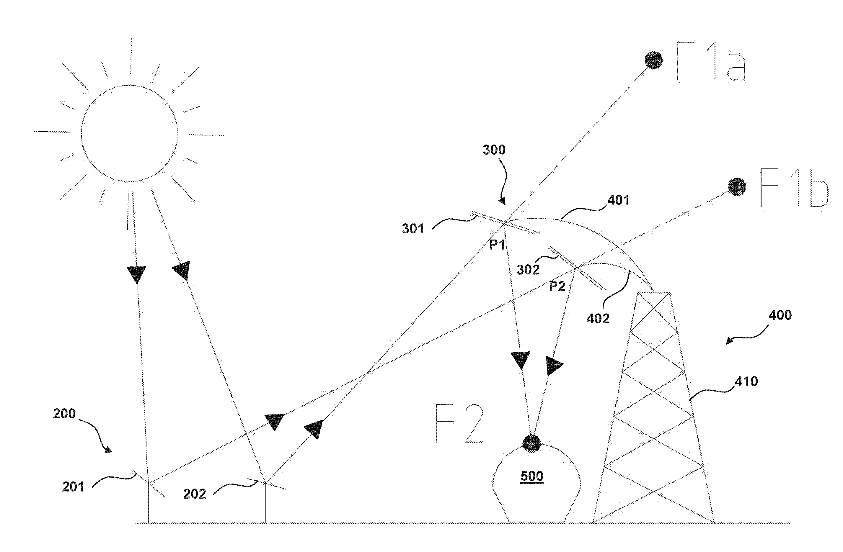
[0041]FIG. 7 shows in schematic way a base embodiment of a secondary optical reflection system according to the present invention. In such figure the secondary system is designated as a whole with 300.

[0042]The optical system 300 is suitable to be used in a plant for storage and / or production of energy of solar origin having an overall configuration of “beam down” type. In particular, the secondary system 300 is associated to a primary optical reflection system designated as a whole with 200 and arranged at the ground.

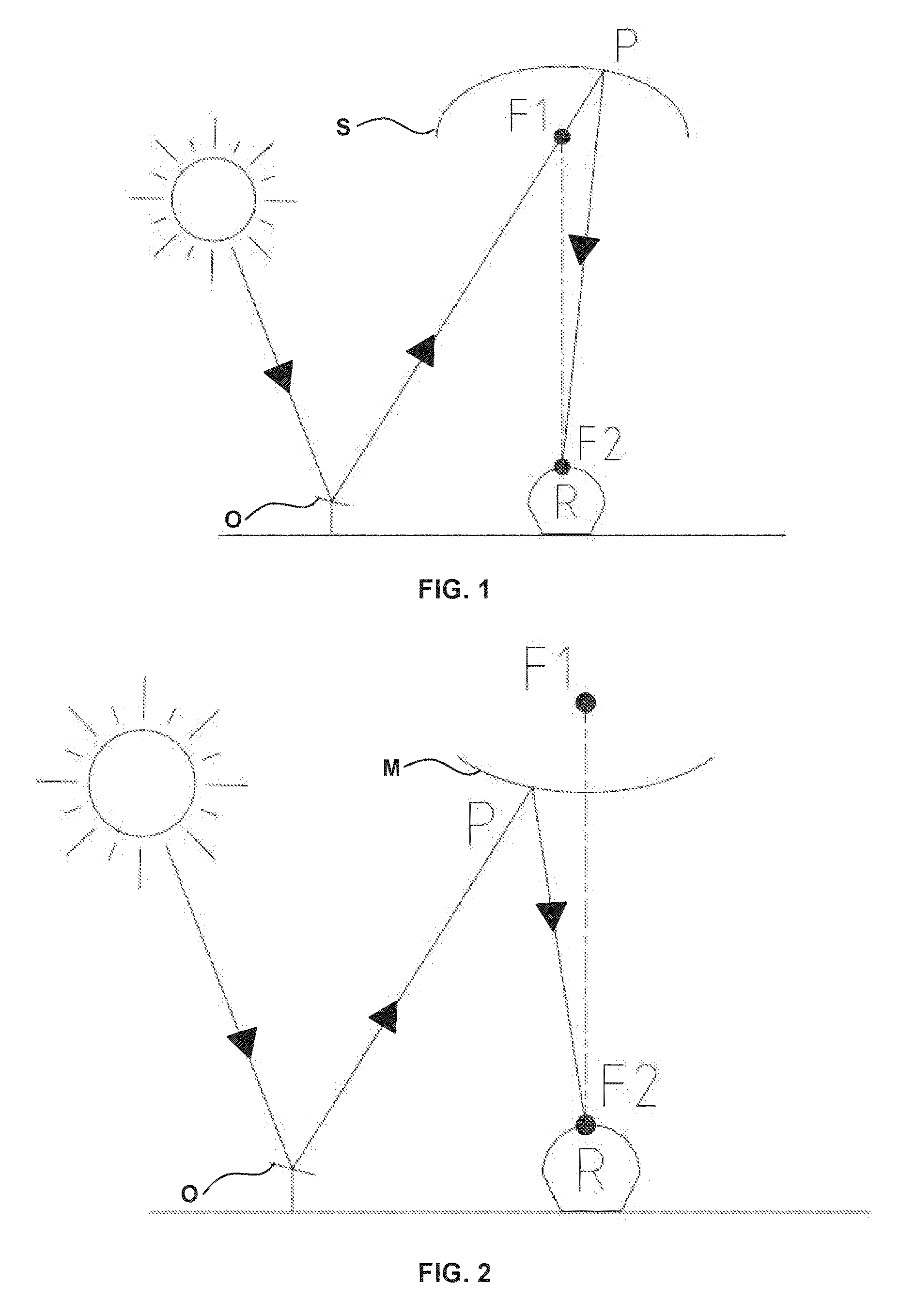
[0043]The primary system 200 is configured so as to reflect the incident solar radiation according to two primary focuses F1a and F1b. To this purpose, the primary system 200, in the represented example, comprises two primary optical reflection elements, respectively 201 and 202, each one indeed suitable to reflect the solar radiation in a respective focus F1a and F1b.

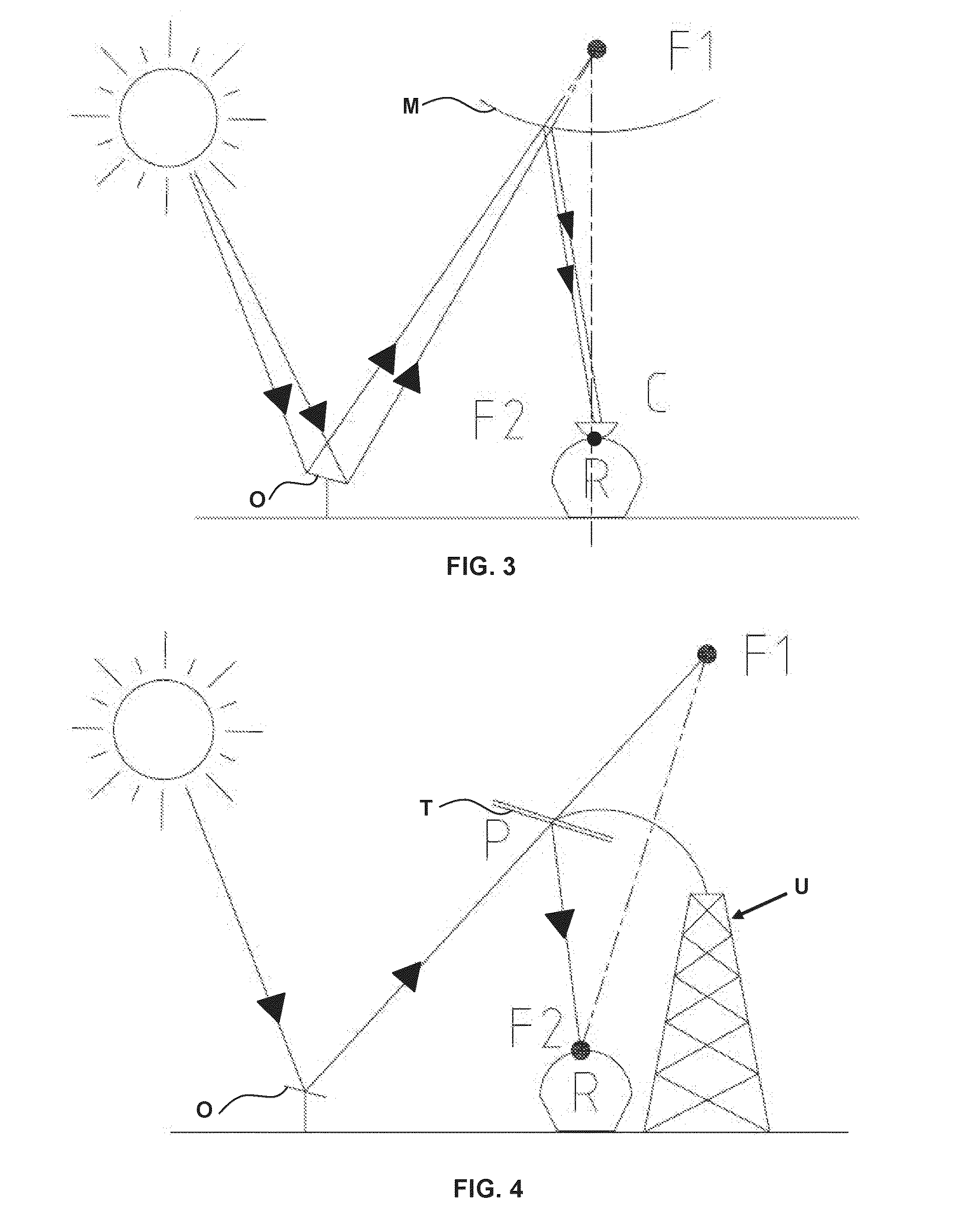
[0044]The secondary system 300 is configured so as to reflect the radiation concentrated at the prima...


PUM


Abstract

A secondary optical system to increase efficiency in collecting solar radiation concentrated by primary mirrors in “beam-down” plant configurations is described. Such secondary optical system is formed at least by two reflectors—preferably in form of plane mirrors arranged at different heights—oriented to associate to each of them a sub-section of a primary field of heliostats. The secondary reflectors—each one associated to a different primary focus F1,i (i=1, . . . , n) corresponding to a sub-set of primary concentrators—allow concentration of solar rays towards a single secondary focus F2.

Description

TECHNICAL FIELD OF THE INVENTION[0001]The present invention relates to a secondary optical system suitable to collect the solar radiation collected (reflexed) by a primary optical system arranged at the ground and to direct (reflect) such solar radiation towards a receiver, placed at the ground too. Such secondary optical reflection system is then conceived to be used in a so-called “beam down” configuration, wherein the solar radiation is concentrated from the top on a receiver placed lower, typically at the ground.[0002]The invention system is particularly suitable to be used in plants for producing thermal and / or electric energy starting from the solar radiation itself (that is in the so-called “thermal solar” or in the “photovoltaic solar” plant).BACKGROUND[0003]In the plants for generating energy of solar origin, the known art is using heliostats—and in particular a field of reflecting mirrors—for concentrating the solar radiation on a determined target, typically a receiver pl...

Claims


Application Information

Patent Timeline
IPC IPC(8): F24S23/77F24S23/79F24S50/20G02B17/00G02B19/00G02B26/08
CPCF24J2/18G02B17/002F24J2/38G02B26/0816G02B19/0042F24S23/77F24S23/79F24S50/20Y02E10/47Y02E10/40
Inventor MAGALDI, MARIO
Owner MAGALDI IND SRL
Why Eureka
Try Eureka