Optical-diffusion film for display and reflective display device using same

a technology of optical diffusion film and reflective display, which is applied in the direction of diffusing elements, mechanical instruments, instruments, etc., can solve the problems of difficult to recognize a predetermined image, shorten the duration of the battery, and lower light intensity from an internal light source or equal to the light intensity of external light, etc., to achieve high contrast display image

Active Publication Date: 2016-03-17
LINTEC CORP +1
View PDF5 Cites 24 Cited by
  • Summary
  • Abstract
  • Description
  • Claims
  • Application Information

AI Technical Summary

Benefits of technology

[0050]When such a configuration is adopted, the reflective display device can accomplish the function satisfactorily even with a monochromatic low-resolution image in these applications, and even in a case in which the reflective plate is provided as a separate body for the reflective display panel, the occurrence of a double image is not likely to pose a problem, and a high contrast display image can be obtained.

Problems solved by technology

In recent years, as a result of popularization of mobile telephones, vehicle-mounted televisions and the like, there are increasing opportunities to view display devices in the outdoors; however, when a display device is viewed in the outdoor, there occurs a problem that the light intensity from an internal light source is lower than or equal to the light intensity of external light, and it is in many cases difficult to recognize a predetermined image.
Furthermore, for mobile applications such as mobile telephones, since the electric power consumption by an internal light source of a display device occupies a large proportion in the total electric power consumption, when the internal light source is heavily used, there is a problem that the duration of the battery is shortened.
However, when these optical-diffusion films are used, since the emission angle of diffused light is simply dependent on the incident angle of external light, there has been a problem that it is difficult to efficiently emit an external light incident from a wide range of angles toward the front of the display device as image display light.

Method used


Image

  • Optical-diffusion film for display and reflective display device using same
  • Optical-diffusion film for display and reflective display device using same
  • Optical-diffusion film for display and reflective display device using same

Examples


example 1

1. Production of Optical-Diffusion Film

[0536](1) Synthesis of Low Refractive Index Polymerizable Compound (B) Component

[0537]In a vessel, 2 moles of isophorone diisocyanate (IPDI) as a component (B1) and 2 moles of 2-hydroxyethyl methacrylate (HEMA) as a component (B3) were introduced relative to 1 mole of a polypropylene glycol (PPG) having a weight average molecular weight of 9,200 as a component (B2), and then the compounds were allowed to react according to a routine method. Thus, a polyether urethane methacrylate having a weight average molecular weight of 9,900 was obtained.

[0538]The weight average molecular weights of polypropylene glycol and polyether urethane methacrylate are values measured by gel permeation chromatography (GPC) under the conditions described below and calculated relative to polystyrene standards.[0539]GPC analyzer: manufactured by Tosoh Corp., HLC-8020[0540]GPC column: manufactured by Tosoh Corp. (in the following, described in the order of passage)[0541]...

example 2

[0583]In Example 2, an optical-diffusion film was produced and evaluated in the same manner as in Example 1, except that when the composition for optical-diffusion film was prepared, an ultraviolet absorber represented by the above formula (10) (manufactured by BASF SA, TINUVIN 384-2) as a component (D) was further added in an amount of 0.5 parts by weight relative to 100 parts by weight of the component (B) (0.2 parts by weight relative to the total amount (100 parts by weight) of the component (A) and the component (B)). The results thus obtained are presented in FIGS. 23 to 27.

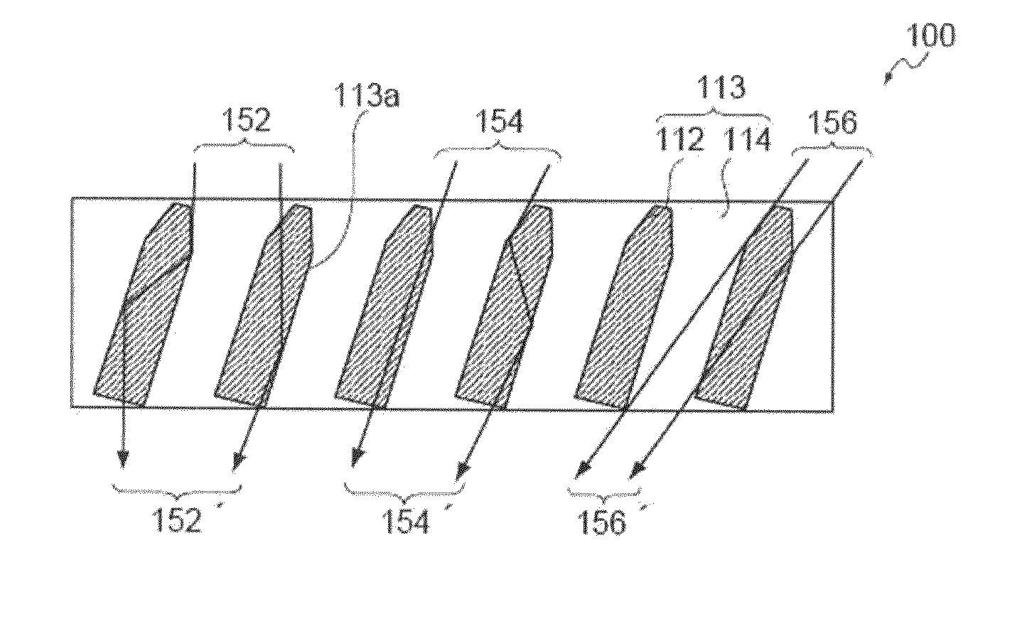
[0584]Here, FIG. 23(a) is a schematic diagram of a cross-section obtained by cutting the optical-diffusion film thus obtained, at a plane that is parallel to the travel direction of the coating layer and orthogonally intersects with the film plane, and FIG. 23(b) is a photograph of the cross-section.

[0585]Furthermore, FIG. 23(c) is a photograph of a cross-section obtained by cutting the optical-diffusion fi...

example 3

[0591]In Example 3, an optical-diffusion film was produced and evaluated in the same manner as in Example 1, except that the film thickness of the coating layer was changed to 210 μm, and at the time of active energy ray irradiation, the coating layer was irradiated with a parallel light having a parallelism of 2° or less such that the angle of irradiation (θ3 in FIG. 14) would be almost 25°, using an ultraviolet spot parallel light source (manufactured by Japan Technology System Corp.) having the central ray parallelism controlled to ±3° or less, instead of irradiating the coating layer with parallel light and then irradiating scattered light while the peeling film was laminated on the exposed surface side of the coating layer. The film thickness of the optical-diffusion film thus obtained was 210 μm. The results thus obtained are presented in FIGS. 28 to 32.

[0592]Here, FIG. 28(a) is a schematic diagram of a cross-section obtained by cutting the optical-diffusion film thus obtained...


PUM

PropertyMeasurementUnit
thicknessaaaaaaaaaa
hazeaaaaaaaaaa
incident angle θ1aaaaaaaaaa

Abstract

Provided are an optical-diffusion film for display which, particularly when applied to a reflective display device, can efficiently diffuse and emit an external light incident from a wide range of angles toward the front of the display device as image display light, and a reflective display device using the optical-diffusion film.
Disclosed is an optical-diffusion film for display, which is a single-layered optical-diffusion film obtained by photocuring a composition for optical-diffusion film including two or more kinds of polymerizable compounds having different refractive indices, and in which the film thickness of the optical-diffusion film has a value within the range of 60 to 700 μm, and when a coating layer formed by applying a composition for optical-diffusion film in a film form is photocured, and the incident angle of incident light with respect to the normal line of the film plane is varied in the range of −70° to 70° along the travel direction of the coating layer at the time of photocuring, the haze value at each incident angle has a value of 70% or more.

Description

TECHNICAL FIELD[0001]The present invention relates to an optical-diffusion film for display, and a reflective display device using the optical-diffusion film.[0002]More particularly, the present invention relates to an optical-diffusion film for display which, when applied to a reflective display device, can efficiently diffuse an external light incident from a wide range of angles toward the front of a display device and emit as an image, and a reflective display device using the optical-diffusion film.BACKGROUND ART[0003]In a display device, conventionally, a predetermined image can be displayed by utilizing light emitted from a light source that is installed inside the device (internal light source).[0004]In recent years, as a result of popularization of mobile telephones, vehicle-mounted televisions and the like, there are increasing opportunities to view display devices in the outdoors; however, when a display device is viewed in the outdoor, there occurs a problem that the lig...

Claims


Application Information

Patent Timeline
Patent Type & Authority Applications(United States)
IPC IPC(8): F21V8/00G02B5/02G02B1/04
CPCG02B5/0236G02B5/0278G02B5/0263G02B6/0051G02B5/0268G02B1/04G02B5/0242G02B5/0257G02B5/0294G02F1/133504G02F2202/023
Inventor KUSAMA, KENTAROKATAGIRI, BAKUORUI, TOMOOSHOSHI, SATORUFUJIKAKE, HIDEOISHINABE, TAKAHIRO
Owner LINTEC CORP
Why Eureka
Try Eureka