Brake apparatus

a technology of brake apparatus and brake function, which is applied in the direction of brake system, brake components, transportation and packaging, etc., can solve the problems of wheel braking function falling, and achieve the effect of assisting the wheel braking, and suppressing the braking function of the wheel

Inactive Publication Date: 2016-03-24
TOYOTA JIDOSHA KK
View PDF8 Cites 40 Cited by
  • Summary
  • Abstract
  • Description
  • Claims
  • Application Information

AI Technical Summary

Benefits of technology

[0013]The second electrical control unit comprises the failure detection means and the backup means. The failure detection means detects a failure of the first hydraulic pressure controller through the communication connection means. When a failure of the first hydraulic pressure controller is detected, the backup means operates the second actuator according to the amount of a brake operation, and assists braking of the wheel. When the first hydraulic pressure controller breaks down, the first actuator outputs the hydraulic pressure outputted from...

Problems solved by technology

However, in a conventional brake apparatus, there is a possibility that a braking function of a wheel may fall, when an actuator for a regene...

Method used


Image

  • Brake apparatus
  • Brake apparatus
  • Brake apparatus

Examples


Embodiment Construction

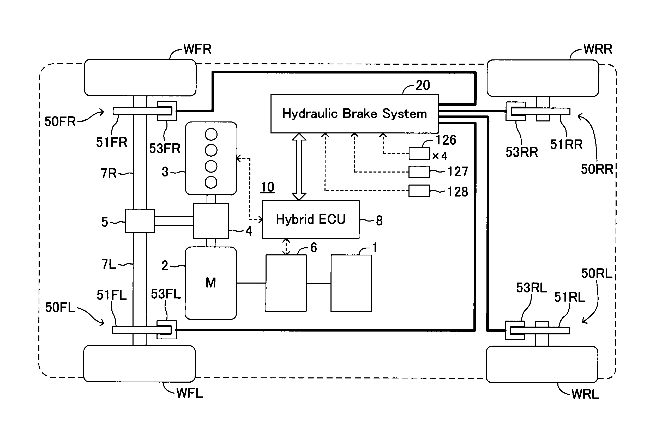
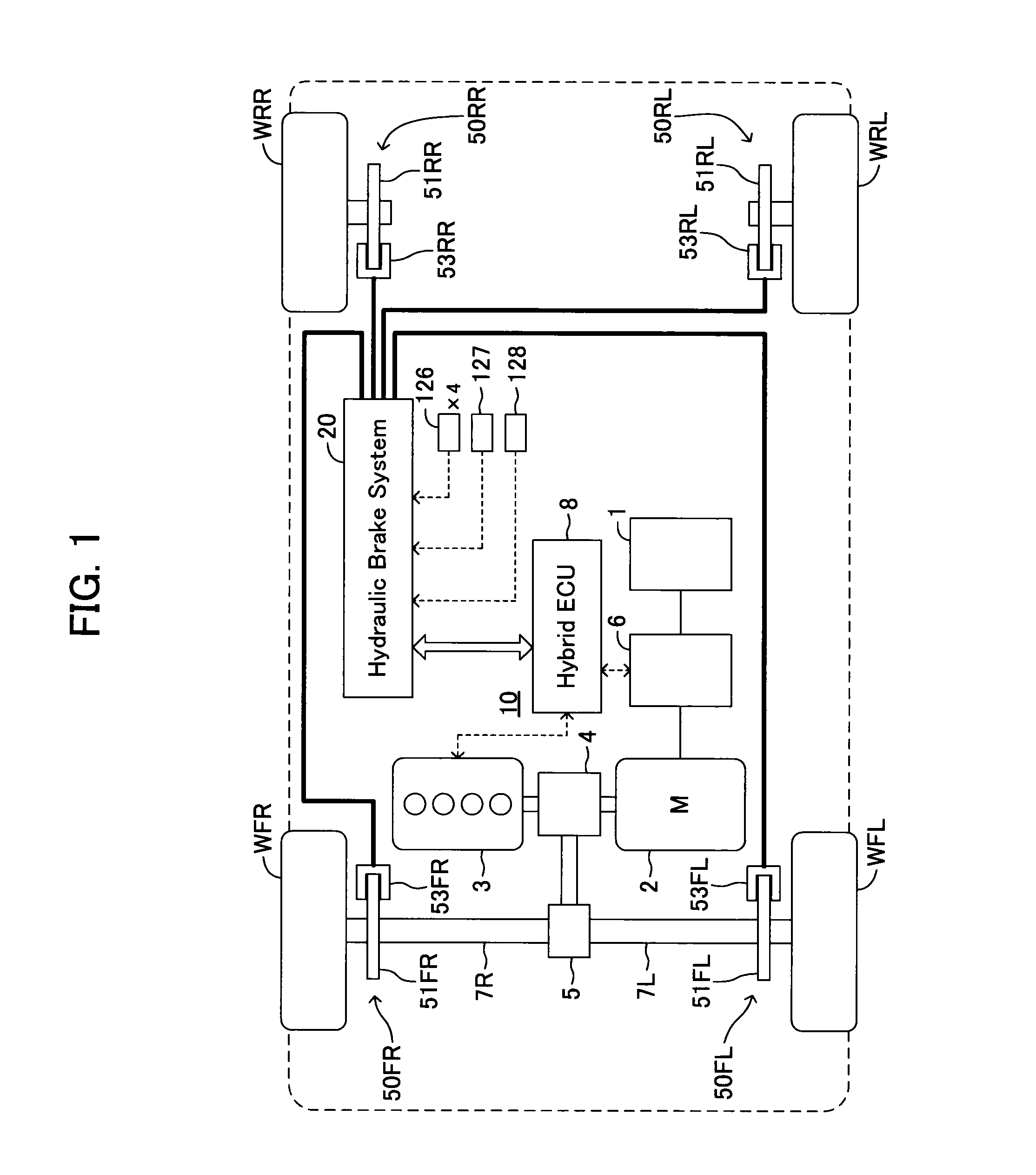
[0041]Hereafter, a brake apparatus for a vehicle according to one embodiment of the present invention will be explained using drawings. FIG. 1 is a schematic structure of a regeneration coordination brake apparatus comprising a brake apparatus according to the present embodiment.

[0042]The brake apparatus according to the present embodiment is applied to a front-wheel-drive-type hybrid vehicle comprising a hybrid system 10 which controls two kinds of power sources, i.e., a motor 2 to which an electric power is supplied from a battery 1 and a gasoline engine 3. In the hybrid system 10, the motor 2 can be used not only as a driving power source, but regenerative braking force can be generated on front, left and right wheels WFL and WFR by using a kinetic energy of a wheel to rotate the motor 2 to generate electricity and collecting the generated electric power in the battery 1. The hybrid vehicle comprises a hydraulic brake system 20 which generates friction braking force on the front,...


PUM


Abstract

A hydraulic brake system includes a first actuator for a regeneration coordination brake control and a second actuator for maintaining the stability of a vehicle in a hydraulic pressure passage between a master cylinder and a wheel cylinder. The first actuator is controlled by a first ECU, and the second actuator is controlled by a second ECU. When a failure occurs in the first actuator or the first ECU, the second ECU operates the second actuator according to the amount of a brake operation, and assists braking of a wheel.

Description

TECHNICAL FIELD[0001]The present invention relates to a brake apparatus applied to a vehicle comprising a regenerative braking device which generates regenerative braking force.BACKGROUND ART[0002]Conventionally, a brake apparatus applied to a vehicle comprising a regenerative braking device which generates regenerative braking force by converting a kinetic energy of a wheel into an electrical energy and collecting the electrical energy into a battery has been known. This brake apparatus comprises a disc brake unit disposed in each wheel, a hydraulic pressure control actuator which controls a hydraulic pressure of a wheel cylinder disposed in the disc brake unit, and an electronic control unit (hereafter, an electronic control unit is referred to as an ECU) which controls an operation of the hydraulic pressure control actuator, in order to generate braking force for covering shortfall of regenerative braking force with friction braking force. The hydraulic pressure control actuator ...

Claims


Application Information

Patent Timeline
IPC IPC(8): B60T8/88B60T7/04B60T13/14
CPCB60T8/885B60T7/042B60T13/146B60T8/321B60T8/4081B60T2270/402B60T2270/604
Inventor NAKAOKA, HIROSHIOOYO, KENTARONIMURA, KAZUNORI
Owner TOYOTA JIDOSHA KK
Why Eureka
Try Eureka