
Heat pump apparatus

a technology of heat pump and heat exchanger, which is applied in the direction of heat pump, lighting and heating apparatus, positive displacement liquid engine, etc., can solve the problems of difficult to maintain high efficiency in operation performed at low speed and low load capacity, high vibration noise level, and significant energy loss, etc., and achieve the effect of stably controlling the operation mod

Active Publication Date: 2016-03-24
MITSUBISHI ELECTRIC CORP
View PDF10 Cites 6 Cited by
  • Summary
  • Abstract
  • Description
  • Claims
  • Application Information

AI Technical Summary

Benefits of technology

This invention is about a heat pump system that can decide if it is running in single or parallel mode and control it stably. This means that the system can automatically adjust its operation mode based on the current needs, which saves energy and makes the system more efficient.

Problems solved by technology

Accordingly, when substantially evaluating annual energy-saving performance, it is a new challenge to increase a COP in the low-load condition that is out of evaluation in the conventional standards.
Further, hitherto, ON-OFF control has been employed as a measure to adjust cooling or heating capacity, but has a problem in that a fluctuation range of temperature adjustment is wide and a vibration noise level is high, and another problem in that an energy loss is significant.
Accordingly, the air-conditioning apparatus is required to maintain high efficiency in a wider operation range and a wider rotation speed range, thereby being difficult to maintain high efficiency in operation performed at low speed and low-load capacity simply by employing control of the rotation speed performed by the related-art inverter.

Method used


Image

  • Heat pump apparatus
  • Heat pump apparatus
  • Heat pump apparatus

Examples


embodiment 1

[Configuration of Two-Cylinder Rotary Compressor 100]

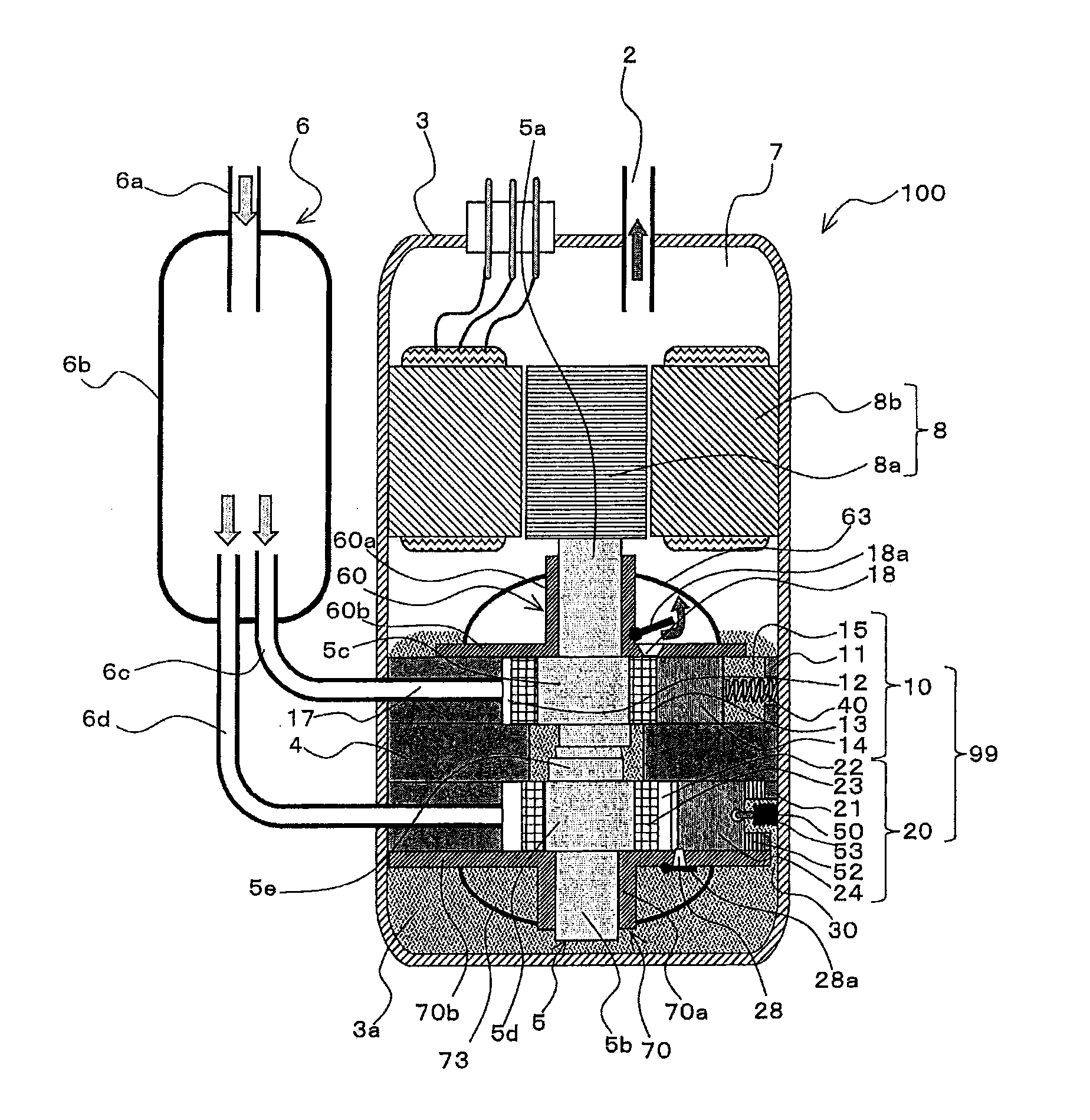
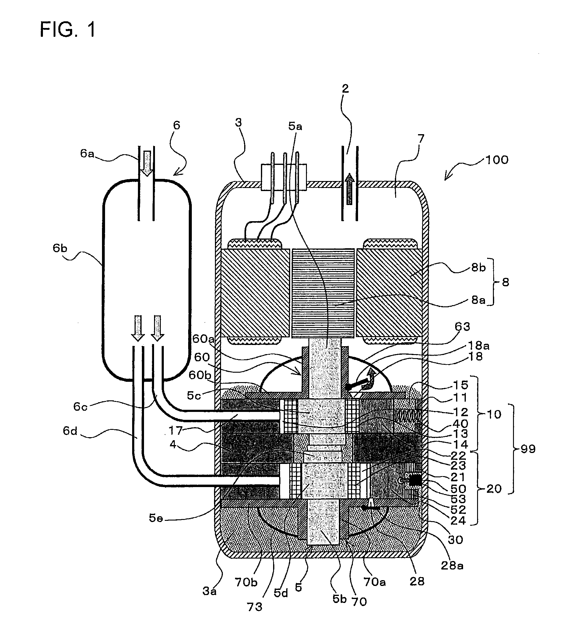
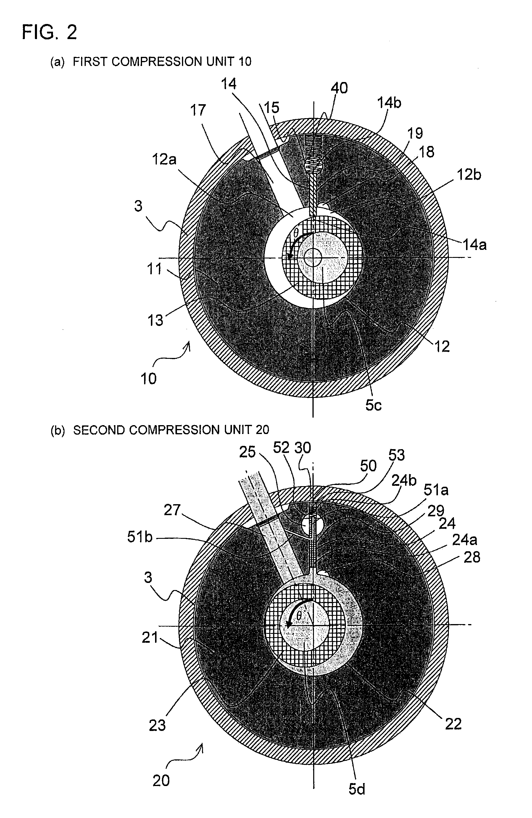
[0039]FIG. 1 is a schematic vertical sectional view of structure of the two-cylinder rotary compressor 100 arranged in a heat pump apparatus according to Embodiment 1 of the present invention, for illustrating a state in which a first compression unit 10 is brought into a steady compression state and a second compression unit 20 is brought into a rest state. Further, FIG. 2 are schematic horizontal sectional views illustrating the structure of the two-cylinder rotary compressor 100 of FIG. 1. FIG. 2(a) is a schematic horizontal sectional view illustrating the first compression unit 10, and FIG. 2(b) is a schematic horizontal sectional view illustrating the second compression unit 20. Note that, FIG. 1 and FIG. 2 are illustrations of the two-cylinder rotary compressor 100 in a state in which the first compression unit 10 is brought into a compression state and the second compression unit 20 is brought into a non-compression state (...

embodiment 2

[0142]Embodiment 2 is different from Embodiment 1 in a method of determining the operation mode. Now, Embodiment 2 according to the present invention is described with reference to the drawings. Note that, in the following, differences of Embodiment 2 from Embodiment 1 are mainly described.

Characteristic Configuration of Two-Cylinder Rotary Compressor 100 of Embodiment 2

[0143]FIG. 12 are schematic side views of a retaining mechanism of the two-cylinder rotary compressor 100 arranged in the heat pump apparatus 200 according to Embodiment 2 of the present invention. FIG. 12(a) is a view illustrating the compression state, and FIG. 12(b) is a view illustrating the non-compression state (rest state).

[0144]The contact component 52, with which the second vane 24 of the second compression unit 20 is brought into contact, is formed of a magnet, and a magnetized conduction plate 45 that is magnetized is mounted on the contact component 52. The magnetized conduction plate 45 is connected thro...

embodiment 3

[0149]Embodiment 3 is different from Embodiment 1 in a method of determining the operation mode. Now, Embodiment 3 according to the present invention is described with reference to the drawings. Note that, in the following, differences of Embodiment 3 from Embodiment 1 are mainly described.

[0150]A principle of determining the operation mode by the operation mode detecting-determining unit 145 according to Embodiment 3 is described.

[0151]FIG. 14 are graphs showing characteristics during the single operation of the two-cylinder rotary compressor 100 of FIG. 7. More specifically, FIG. 14(a) is a graph showing a waveform obtained by calculating a torque fluctuation during the single operation based on the current waveform of the inverter output (FIG. 10(a)). FIG. 14(b) is a bar graph showing intensities of respective frequency components (square of a torque value) obtained by subjecting this torque fluctuation waveform to the FFT analysis. Similarly, FIG. 15 are graphs showing character...


PUM


Abstract

A heat pump apparatus, including: a two-cylinder compressor including: an electric motor; two compression units to be driven by the electric motor, the two-cylinder compressor being structured to switch between two operation modes including single operation in which one of the compression units is brought into a non-compression state, and parallel operation in which both the compression units are brought into a compression state; an inverter drive control device supplying drive power to the electric motor of the two-cylinder compressor; an operation mode detecting-determining unit determining a current operation mode based on an electric signal acquired from the inverter drive control device; and a capacity control device determining a rotating frequency of the electric motor so that a temperature of a target object is brought close to a set value, to thereby control the inverter drive control device based on a result of determination of the operation mode detecting-determining unit.

Description

TECHNICAL FIELD[0001]The present invention relates to a heat pump apparatus using a compressor including two cylinders or two compression units.BACKGROUND ART[0002]Hitherto, in a heat pump apparatus such as an air-conditioning apparatus or a water heater, a vapor-compression refrigeration cycle using a refrigerant compressor is generally employed. That is, the vapor-compressor refrigeration cycle constructed by connecting the refrigerant compressor, a condenser, a pressure reducing unit, and an evaporator to each other through pipes is installed in the heat pump apparatus, thereby being capable of carrying out operation in accordance with intended use (such as air-conditioning use and hot water supply use).[0003]Incidentally, in recent years, regulations on greenhouse gas emission were incorporated in the Kyoto Protocol in 1997 from the viewpoint of preventing global warming, and the Kyoto Protocol came into force as international law in 2005. In order to reduce the amount of carbon...

Claims


Application Information

Patent Timeline
IPC IPC(8): F25B30/02F04C23/00F04C28/02F25B31/02
CPCF25B30/02F04C28/02F04C23/001F25B31/026F04C28/08F04C18/356F25B1/02F25B13/00F25B49/022F25B2313/0314F25B2313/0315F25B2400/074F25B2600/021F25B2700/2104F25B2700/2106F04C23/008F04C29/04F04C28/065F04C2270/80F04C2270/86F04C2270/035Y02B30/70
Inventor YOKOYAMA, TETSUHIDESHINOMOTO, YOSUKEMOROE, SHOGOSATAKE, AKIRAFUJITSUKA, MASASHIMORI, TAKESHIKATO, TAROMAEYAMA, HIDEAKITADA, KEIKO
Owner MITSUBISHI ELECTRIC CORP
Learn More