Adaptive electronically steerable array (AESA) system for interceptor RF target engagement and communications

a technology of electronic steerable arrays and interceptors, applied in direction controllers, weapons, ammunition projectiles, etc., can solve problems such as difficult detection over background noise, and achieve the effects of saving weight, volume, cost and complexity, and more flexibility in design

Active Publication Date: 2016-03-24
RAYTHEON CO
View PDF15 Cites 4 Cited by
  • Summary
  • Abstract
  • Description
  • Claims
  • Application Information

AI Technical Summary

Benefits of technology

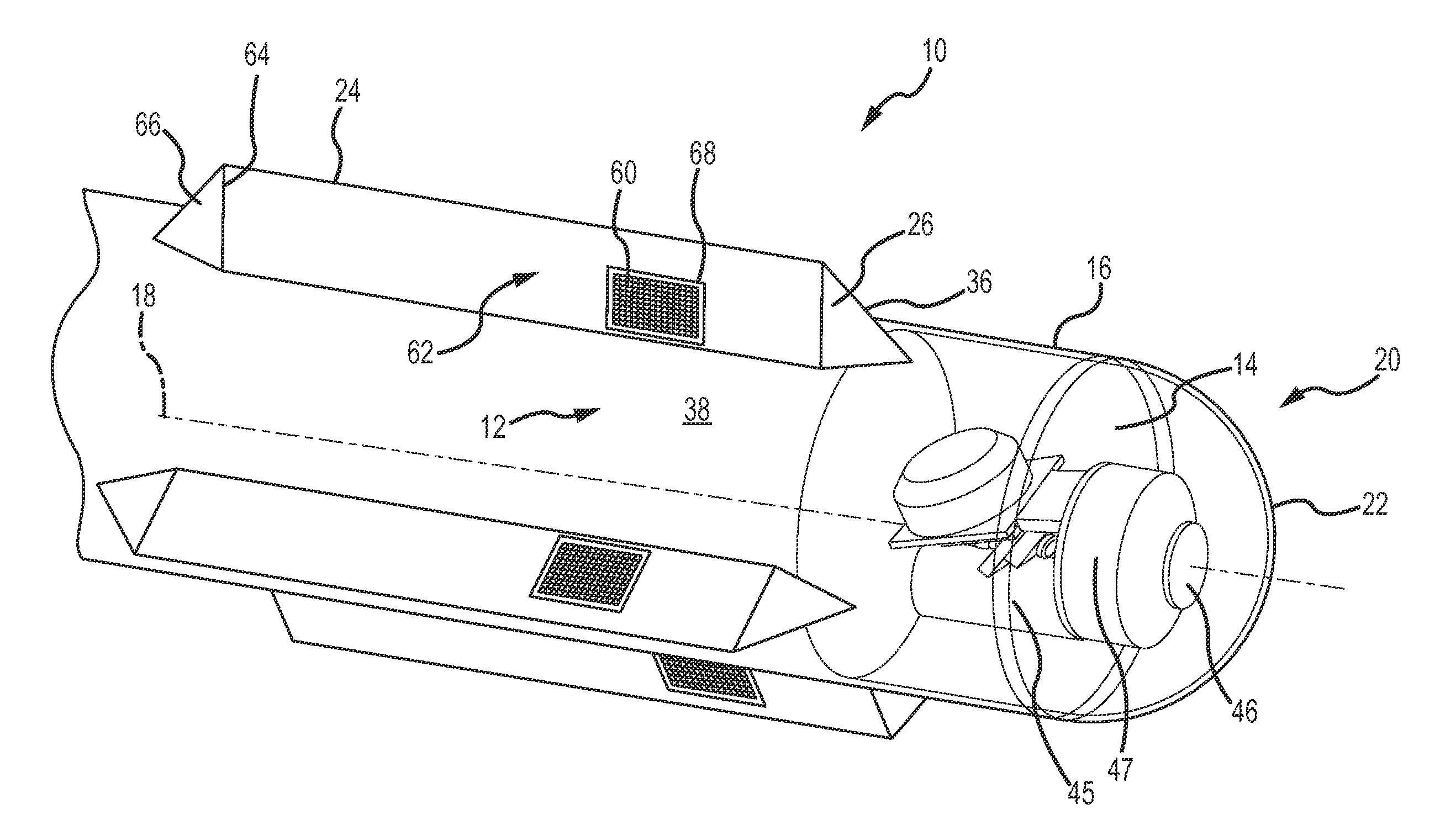
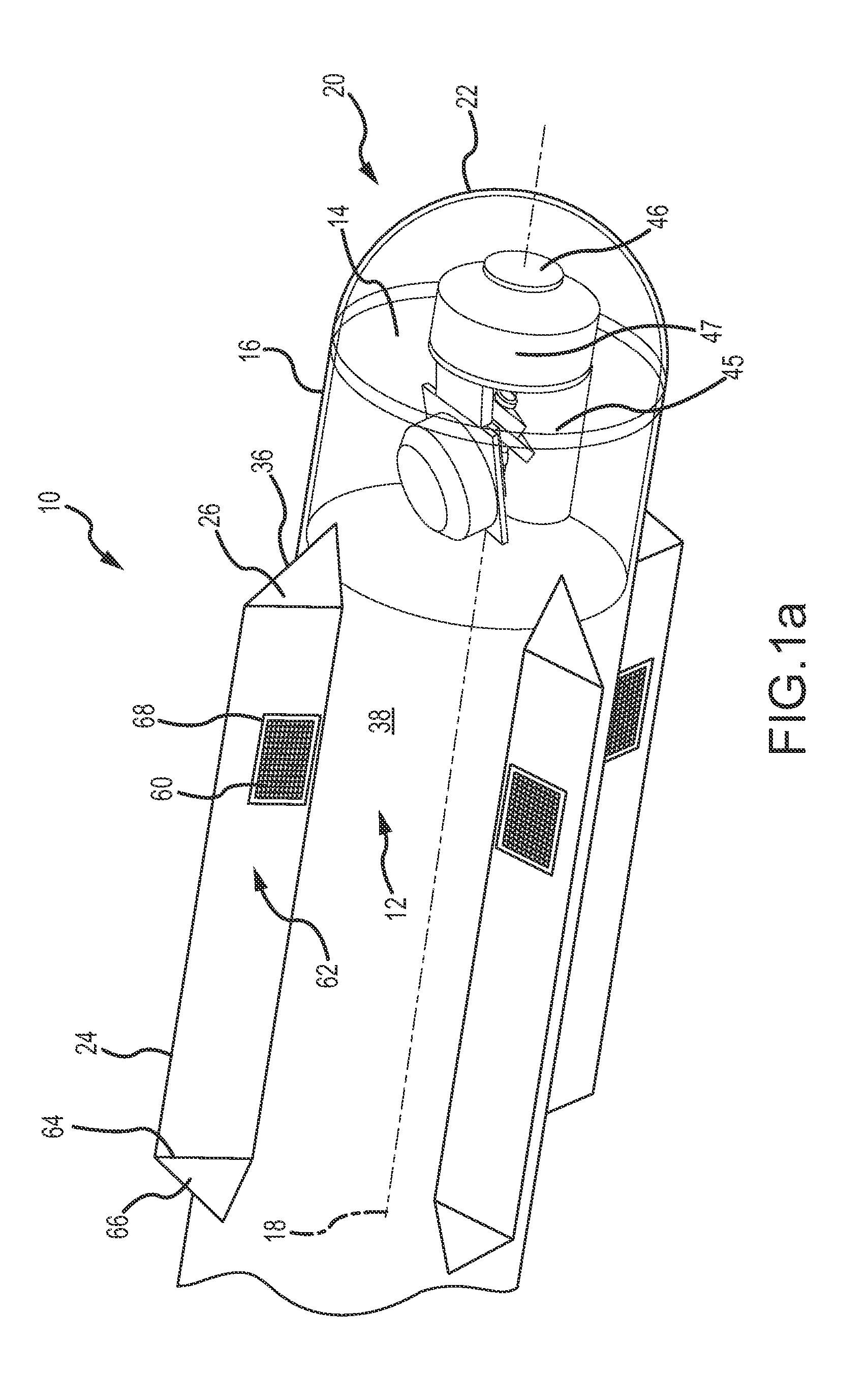
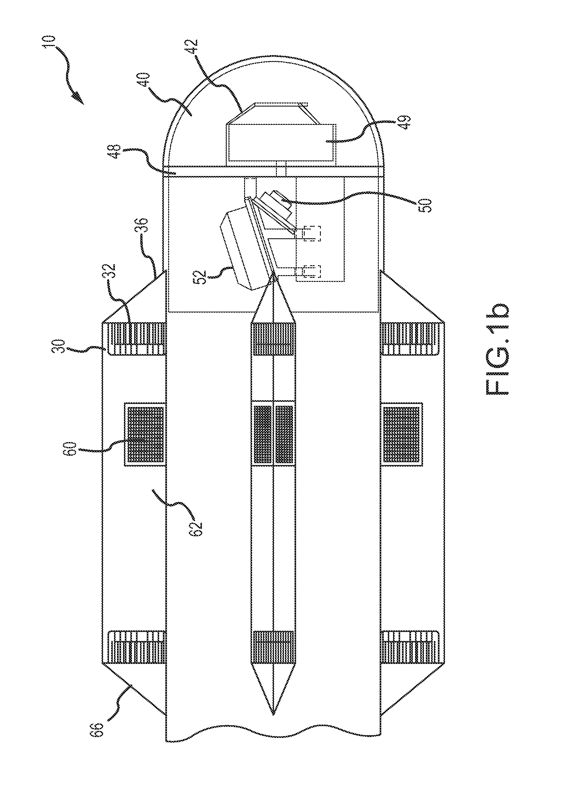
[0013]In an embodiment, the AESA system is paired with an IR system for dual-mode operation. The IR system is mounted behind a dome on the nose of the interceptor. Because the AESA system is not co-located with the IR system in the dome, there is considerably more flexibility to design the IR sys

Problems solved by technology

Advanced AESA radars can improve on the older passive electronically scanned array (PESA) radars by spreading their signal emissions out across a band of frequenc

Method used


Image

  • Adaptive electronically steerable array (AESA) system for interceptor RF target engagement and communications
  • Adaptive electronically steerable array (AESA) system for interceptor RF target engagement and communications
  • Adaptive electronically steerable array (AESA) system for interceptor RF target engagement and communications

Examples


Embodiment Construction

[0023]The present invention describes an AESA system for RF target engagement and communications for interceptor. The AESA system comprises multiple arrays that are deployed on aerodynamic control surfaces of the interceptor. The arrays may be controlled independently or in concert for RF target engagement or communications. The AESA system may be paired with an IR system for dual-mode operation. Removal of the AESA system from the interceptor radome increases the design options for implementation of the IR system. For example, the dual-mode system may be able to eliminate the mechanical gimbal for the IR seeker and use an axisymmetric dome without sacrificing performance.

[0024]The interceptor may be any airborne vehicle that includes aerodynamic control surfaces. These surfaces may provide lift or maneuverability, may be fixed or moveable. For example, the interceptor may be a self-propelled missile, a gun-launched projectile, a unmanned aerial vehicle (UAV), a manned aircraft or a...


PUM


Abstract

An AESA system comprises a plurality of arrays, each comprising a plurality of radiating elements, each array configured for placement on a forward-facing surface of a different one of a plurality of aerodynamic control surfaces on an interceptor. A plurality of RF transmissive radome elements, each having an aerodynamic shape complementary to the aerodynamic control surface, are placed over one of the arrays. Control circuitry configures the arrays, independently or in concert, for RF target engagement and communication. Additional arrays may be positioned on side or aft-facing surfaces of the aerodynamic control surfaces for RF communication. The AESA system may be paired with an ER system for dual-mode operation.

Description

BACKGROUND OF THE INVENTION[0001]1. Field of the Invention[0002]This invention relates to adaptive electronically steerable arrays (AESAs), and more particularly to an AESA system for a missile interceptor comprising multiple AESA arrays positioned on forward facing surfaces of the interceptor's aerodynamic control surfaces for RF target tracking and communications. Deployment of the AESA arrays on the aerodynamic control surfaces frees up volume, thus increasing design options for an IR seeker.[0003]2. Description of the Related Art[0004]Interceptors may be configured to use the RF band for target engagement (e.g. search, acquisition, targeting or terminal engagement) or for communications with another communication station (e.g. another interceptor, a different airborne platform, or ground or sea based system). Historically, the RF antenna would have been positioned behind the radome and had a fixed beam pattern within a field-of-view (FOV), either forward or side-looking. To incr...

Claims


Application Information

Patent Timeline
IPC IPC(8): F41G7/20F42B30/00F42B15/01H01Q1/28H01Q1/42H01Q3/24
CPCF42B30/006H01Q1/42F41G7/20H01Q1/28F42B15/01H01Q3/24F41G7/008F41G7/2246F41G7/2253F41G7/2286F41G7/2293H01Q1/287H01Q21/061
Inventor FACCIANO, ANDREW, B.KREBS, RODNEY, H.BIELAS, MICHAEL, S.TRETSCHOK, CODY, D.SPANGLER, MICHAEL, S.MITCHELL, BENJAMIN
Owner RAYTHEON CO
Why Eureka
Try Eureka