
Gas detecting device and method thereof

a gas detection and detection device technology, applied in the direction of measurement devices, instruments, specific gravity measurements, etc., can solve the problem of difficult detection of low-concentration voc, and achieve the effect of broadening the detection concentration range of target gases and high sensitivity

Active Publication Date: 2016-03-24
FUJI ELECTRIC CO LTD
View PDF1 Cites 14 Cited by
  • Summary
  • Abstract
  • Description
  • Claims
  • Application Information

AI Technical Summary

Benefits of technology

The patent aims to provide a gas detecting device and method that can detect target gases with high sensitivity and extend the detection range to low concentrations. The device is designed to drive a semiconductor gas sensor. This technology can be used in various applications to detect the presence of target gases with high precision.

Problems solved by technology

However, since the conventional semiconductor gas sensor used for detecting a gas leak and incomplete combustion has insufficient sensitivity, it is difficult to detect low-concentration VOC.
However, the semiconductor gas sensors disclosed in the above patent documents are not designed to sense gases having a concentration as low as 0.001 to 1 ppm.

Method used


Image

  • Gas detecting device and method thereof
  • Gas detecting device and method thereof
  • Gas detecting device and method thereof

Examples


example 1

[0088]Subsequently, the characteristics of the gas detecting device and the gas detection method according to the present disclosure were examined while changing the driving conditions. The characteristics are illustrated in Table 1.

TABLE 1Driving ConditionsT0 = T2 = T3T1t0 = t2 = t3t1Gas SensitivityExample A220° C.20° C.0.6 s20 s77.2Example B270° C.20° C.0.6 s20 s112.5Example C430° C.20° C.0.6 s20 s78.0Example D320° C.20° C.0.1 s20 s41.3Example E320° C.20° C.0.2 s20 s79.7Example F320° C.20° C.0.6 s20 s134.0Example G320° C.20° C.0.6 s10 s66.0Example H320° C.20° C.0.6 s 5 s22.8Comparative270° C.———1.0Example AComparative320° C.———1.0Example B

[0089]Moreover, FIG. 8 illustrates a driving pattern diagram for describing a heater layer driving scheme illustrated in Table 1. In the case of Examples A to H, the target gas desorption step and the target gas detection step were performed in parallel as described above and were examined for comparison using the pattern of T12≦T0. A material wh...

example 2

[0097]Next, experiments were conducted to verify whether the gas detecting device of the present disclosure is actually sensitive to a low-concentration target gas. The sensitivity was verified for ethanol, acetone, and isoprene which is VOC as a target gas. A sample gas that contains one of ethanol, acetone, and isoprene in low concentration (1 ppm or lower) was generated, and the sensitivity of the gas detecting device for this sample gas was examined. In this case, the best condition was examined while changing the driving conditions.

[0098]When the target gas was acetone, highest sensitivity was obtained under a driving condition that the target gas adsorption period t1 was 30 s, the target gas desorption period t2 was 700 ms, and the heater voltage for realizing the target gas desorption temperature was 1.45 V. It was verified from an experiment that the target gas was detected in concentration as low as 1 ppm or lower, as illustrated in FIG. 10.

[0099]When the target gas was eth...


PUM

PropertyMeasurementUnit
temperatureaaaaaaaaaa
thicknessaaaaaaaaaa
grain sizeaaaaaaaaaa

Abstract

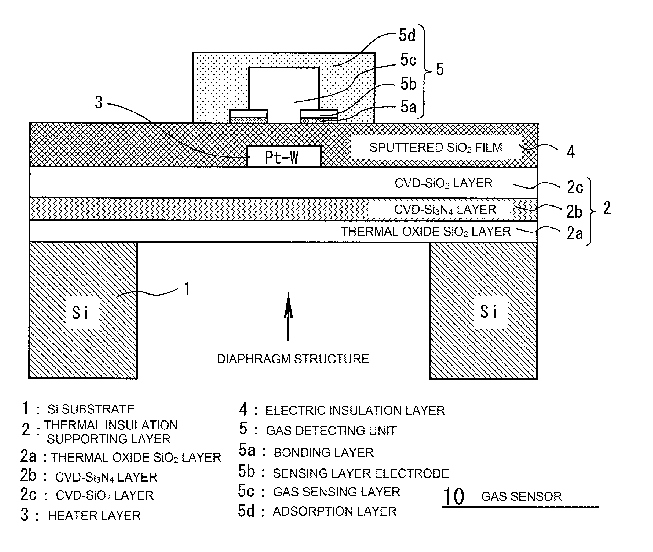
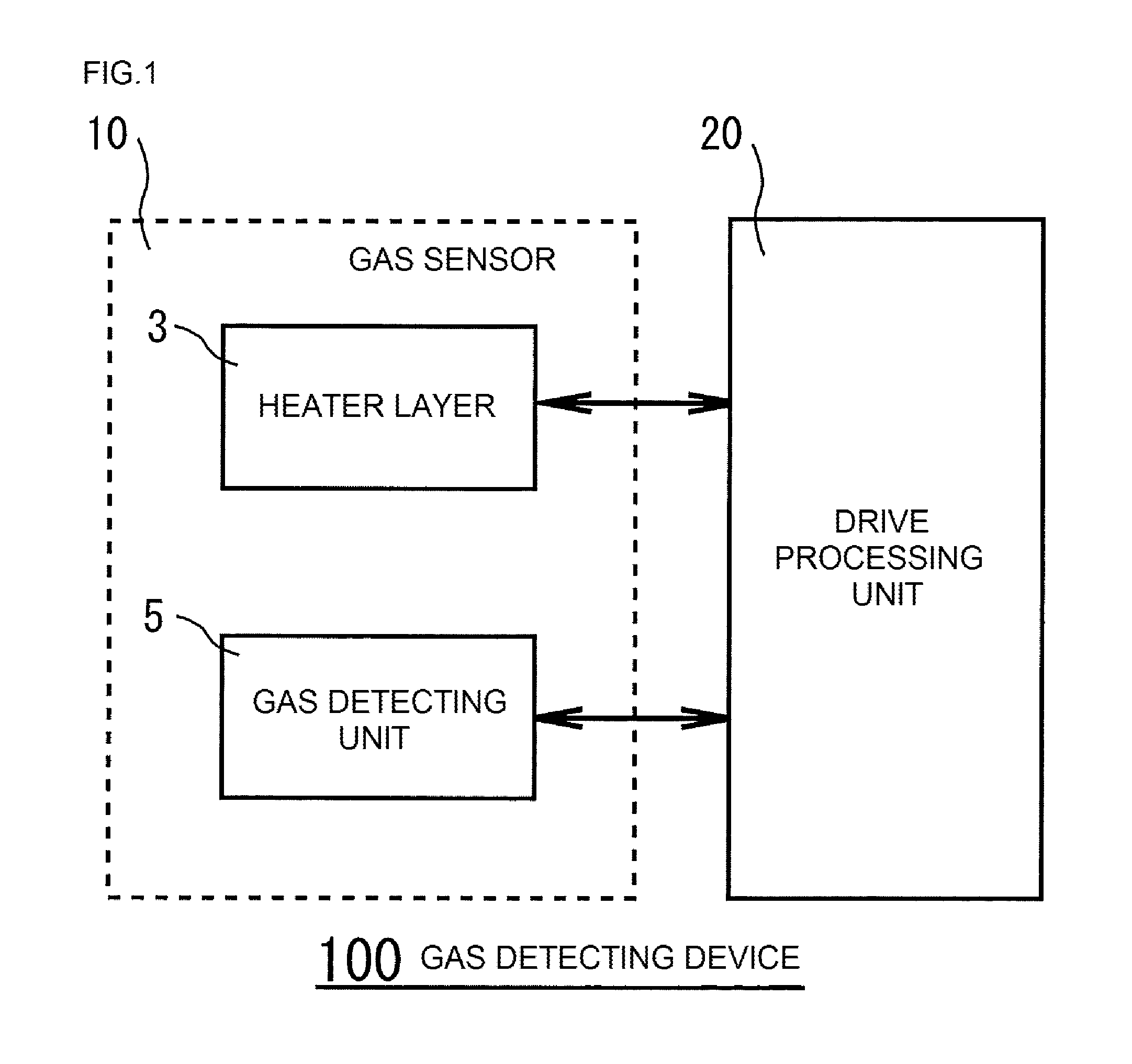
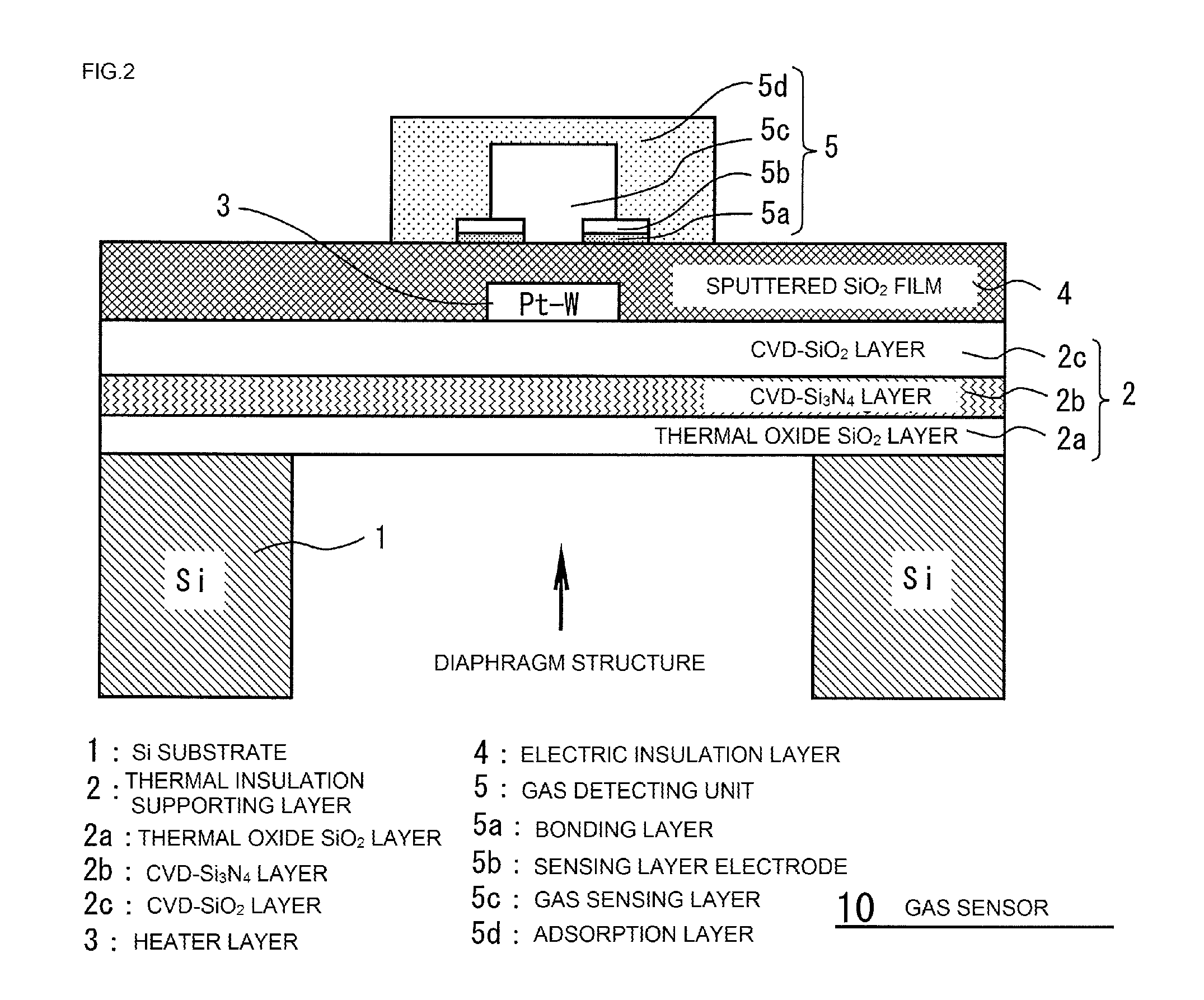
A gas detecting method includes heating a gas detector, formed of a gas sensing layer and an adsorption layer, for an oxygen adsorption period t0 at an oxygen adsorption temperature T0; heating the gas detector for a target gas adsorption period t1 at a target gas adsorption temperature T1 at which a target gas is adsorbed to the adsorption layer, heating the gas detector for a target gas desorption period t2 at a target gas desorption temperature T2 at which the target gas adsorbed to the adsorption layer is desorbed to move to the gas sensing layer; and calculating a gas concentration of the target gas from a sensor resistance of the gas sensing layer. A gas detecting device includes the gas detector and a drive processing unit configured to carry out the method.

Description

CROSS-REFERENCE TO RELATED APPLICATIONS[0001]This application is a continuation application, filed under 35 U.S.C. §111(a), of International Application PCT / JP2014 / 082659 filed on Dec. 10, 2014, and claims benefit of foreign priority to Japanese Patent Application 2013-257735 filed Dec. 13, 2013, the disclosure of each of which is incorporated herein by reference.BACKGROUND[0002]1. Field[0003]The present disclosure relates to a gas detecting device that detects gases having a concentration as low as ppb levels and a method thereof.[0004]2. Related Art[0005]A semiconductor gas sensor is a device that is selectively sensitive to a specific gas, such as, for example, methane gas (CH4), propane gas (C3H8), butane gas (C4H10), or carbon monoxide (CO). The principle and structure of the semiconductor gas sensor are relatively simple, and can be mass-produced easily at low cost.[0006]Such a semiconductor gas sensor is broadly used for detecting a gas leak and incomplete combustion. A gas l...

Claims


Application Information

Patent Timeline
Patent Type & Authority Applications(United States)
IPC IPC(8): G01N27/12
CPCG01N27/12G01N27/16
Inventor SUZUKI, TAKUYA
Owner FUJI ELECTRIC CO LTD
Learn More