Semiconductor package having cascaded chip stack

a technology of cascaded chip and semiconductor, applied in the direction of semiconductor/solid-state device details, semiconductor devices, electrical apparatus, etc., can solve the problems of easy warpage or damage of the upper semiconductor chip, and achieve the effect of preventing bonding failure and small mold thickness

Active Publication Date: 2016-03-24
SAMSUNG ELECTRONICS CO LTD
View PDF4 Cites 33 Cited by
  • Summary
  • Abstract
  • Description
  • Claims
  • Application Information

AI Technical Summary

Benefits of technology

[0007]A semiconductor package capable of preventing a bonding failure between semiconductor chips bonded in a flip chip bonding method while maintaining a small mold thickness is disclosed herein.

Problems solved by technology

Because of this, when the upper semiconductor chip is bonded on the lower semiconductor chip, it is easy to warp or damage the upper semiconductor chip.

Method used


Image

  • Semiconductor package having cascaded chip stack
  • Semiconductor package having cascaded chip stack
  • Semiconductor package having cascaded chip stack

Examples


Embodiment Construction

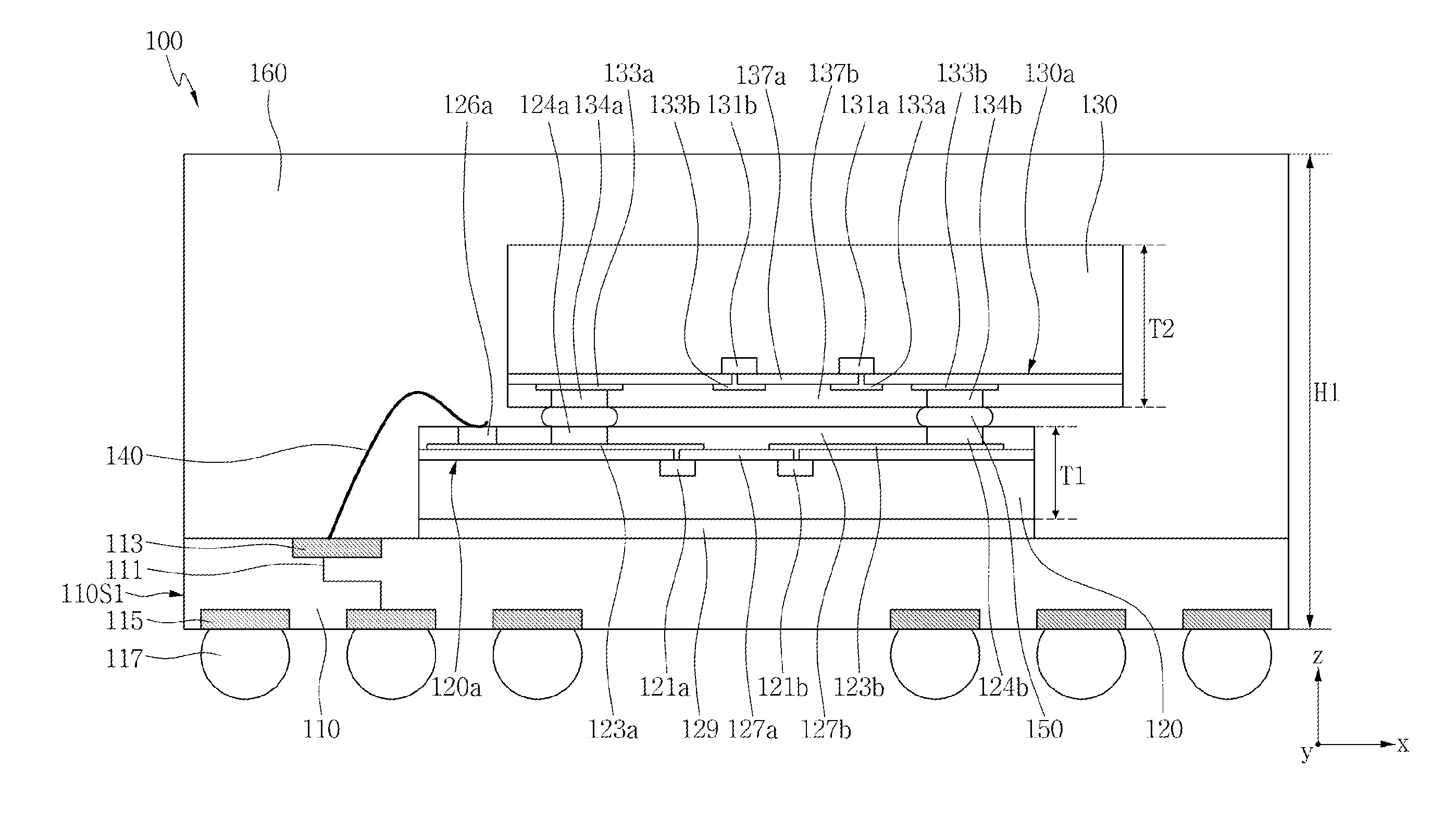
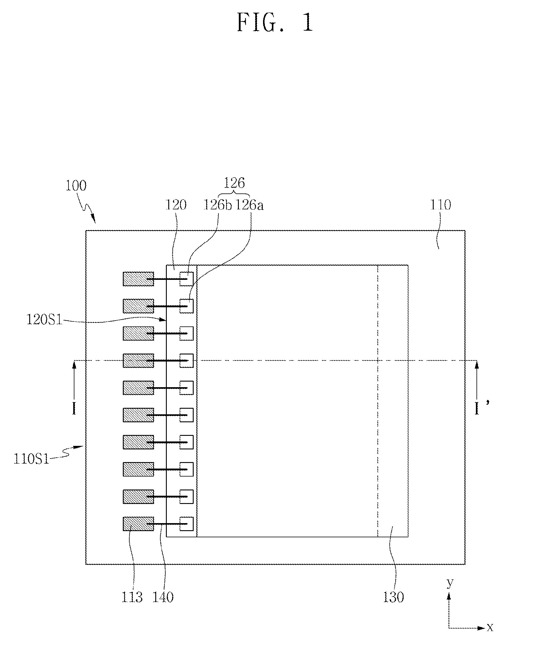
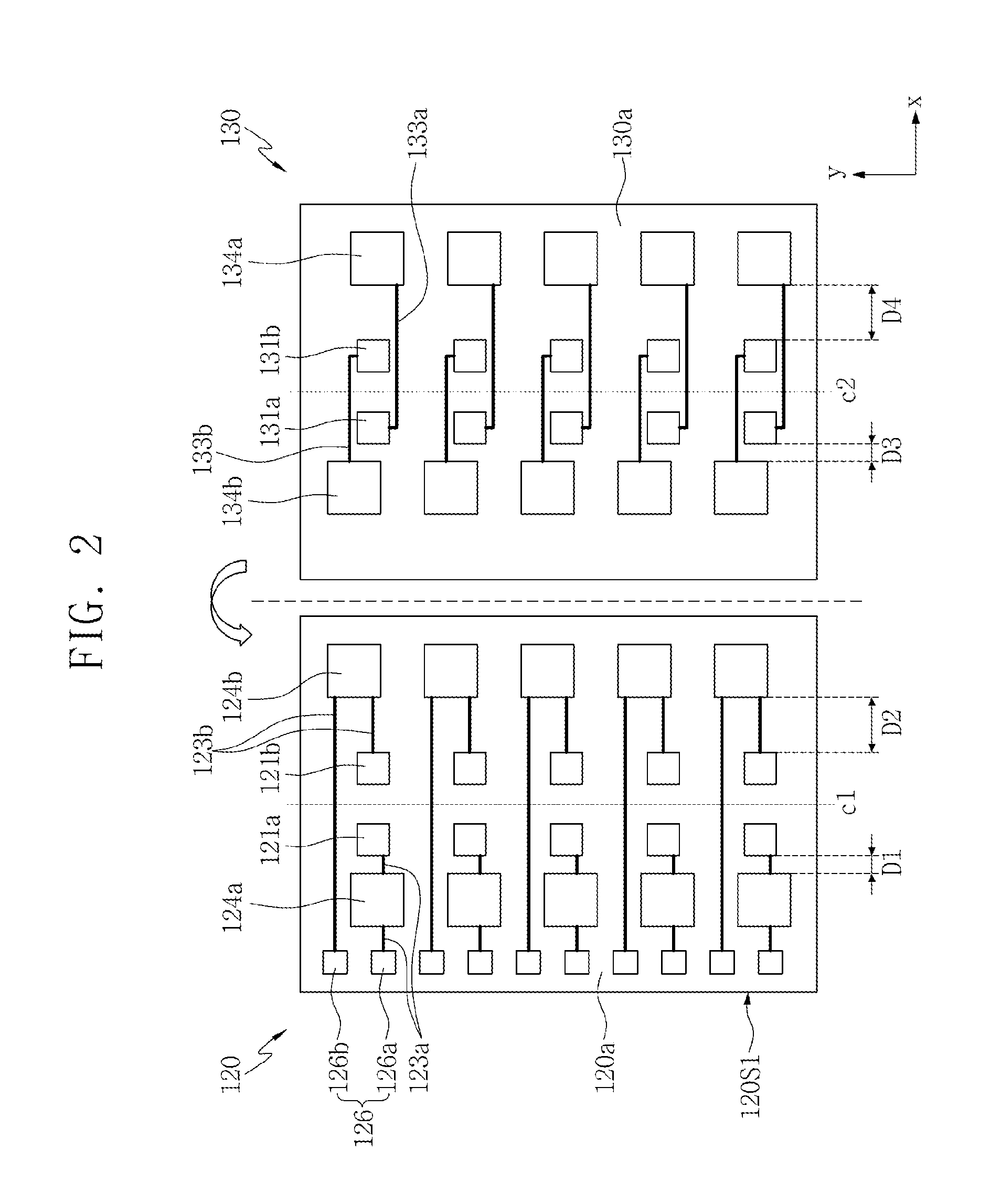
[0026]Advantages and features of the technology disclosed and described herein and methods of accomplishing them will be made apparent with reference to the accompanying drawings and the embodiments to be described below. The concepts presented may, however, be embodied in various different forms, and should be construed as limited, not by the embodiments set forth herein, but only by the claims.

[0027]The terminology used herein is for the purpose of describing particular embodiments only and is not intended to be limiting of the present inventive concept. As used herein, the singular forms “a,”“an,” and “the” are intended to include the plural forms as well, unless the context clearly indicates otherwise. It will be further understood that the terms “comprises,” and / or “comprising,” when used in this specification, specify the presence of stated features, integers, steps, operations, elements, and / or components, but do not preclude the presence or addition of one or more other feat...


PUM


Abstract

A semiconductor package that includes a package substrate, a lower semiconductor chip mounted on the package substrate, and an upper semiconductor chip stacked on the lower semiconductor chip in a cascade shape is provided. An active surface of the lower semiconductor chip is facing an active surface of the upper semiconductor chip.

Description

CROSS-REFERENCE TO RELATED APPLICATION[0001]This application claims priority under 35 U.S.C. §119 to Korean Patent Application No. 10-2014-0125233 filed on Sep. 19, 2014, the disclosure of which is hereby incorporated by reference in its entirety.BACKGROUND[0002]1. Field[0003]Embodiments of a semiconductor package having a cascaded chip stack are disclosed herein.[0004]2. Description of Related Art[0005]Recently, to increase an operational speed of mobile dynamic random access memory (DRAM) and to meet high capacity needs, a mirror die package (MDP) structure has been developed. Since a conventional MDP structure has a structure in which an upper semiconductor chip is bonded on a lower semiconductor chip in a flip chip bonding method, which is bonded to a substrate in a wire bonding method, a wire used in a wire bonding method is located between the lower semiconductor chip and the upper semiconductor chip. To this end, a distance between the lower semiconductor chip and the upper s...

Claims


Application Information

Patent Timeline
Patent Type & Authority Applications(United States)
IPC IPC(8): H01L23/00H01L25/065H01L23/498
CPCH01L25/0657H01L2924/14H01L24/49H01L24/73H01L23/49838H01L2225/06562H01L2225/06513H01L2225/0651H01L2224/73207H01L2224/16148H01L2224/48227H01L2224/48106H01L2224/17181H01L2924/1434H01L2924/143H01L24/17H01L2224/05569H01L2224/92242H01L2224/92163H01L23/3128H01L24/16H01L24/29H01L24/32H01L24/48H01L24/92H01L25/50H01L2224/0401H01L2224/04042H01L2224/0603H01L2224/06135H01L2224/16145H01L2224/2919H01L2224/32225H01L2224/49175H01L2224/73265H01L2224/92247H01L2924/1436H01L2924/1438H01L2924/15311H01L2224/05554H01L2924/00014H01L2924/181H01L2224/85424H01L2224/85447H01L2224/85455H01L2924/15184H01L24/06H01L2224/05014H01L2224/4847H01L2224/023H01L2924/00012H01L2924/00H01L2224/45099H01L2224/45015H01L2924/207H01L2224/05599H01L2924/0001H01L23/4012
Inventor CHO, YUN-RAE
Owner SAMSUNG ELECTRONICS CO LTD
Why Eureka
Try Eureka