
Package for electronic parts, lid thereof, material for the lid and method for producing the lid material

a technology for electronic parts and lids, applied in the field of electronic component packages, can solve the problems of reducing hermeticity, seam welding, electron beam welding, etc., and achieve the effects of suppressing thermal stress, preventing the breakage of the case and bonding failure, and quick fusion of the brazing material layer

Inactive Publication Date: 2005-07-26
DAISHINKU CORP +1
View PDF8 Cites 4 Cited by
  • Summary
  • Abstract
  • Description
  • Claims
  • Application Information

AI Technical Summary

Benefits of technology

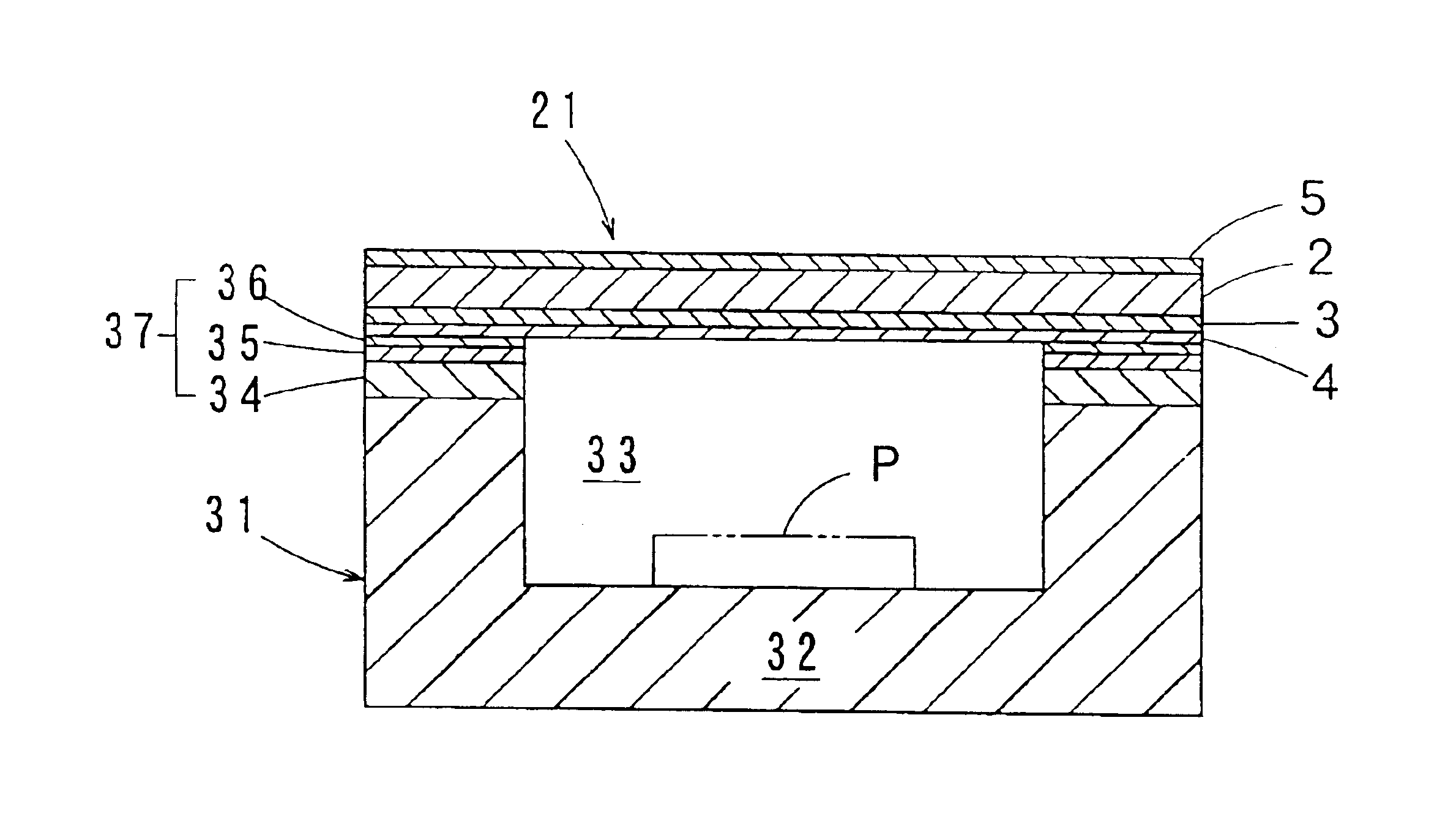
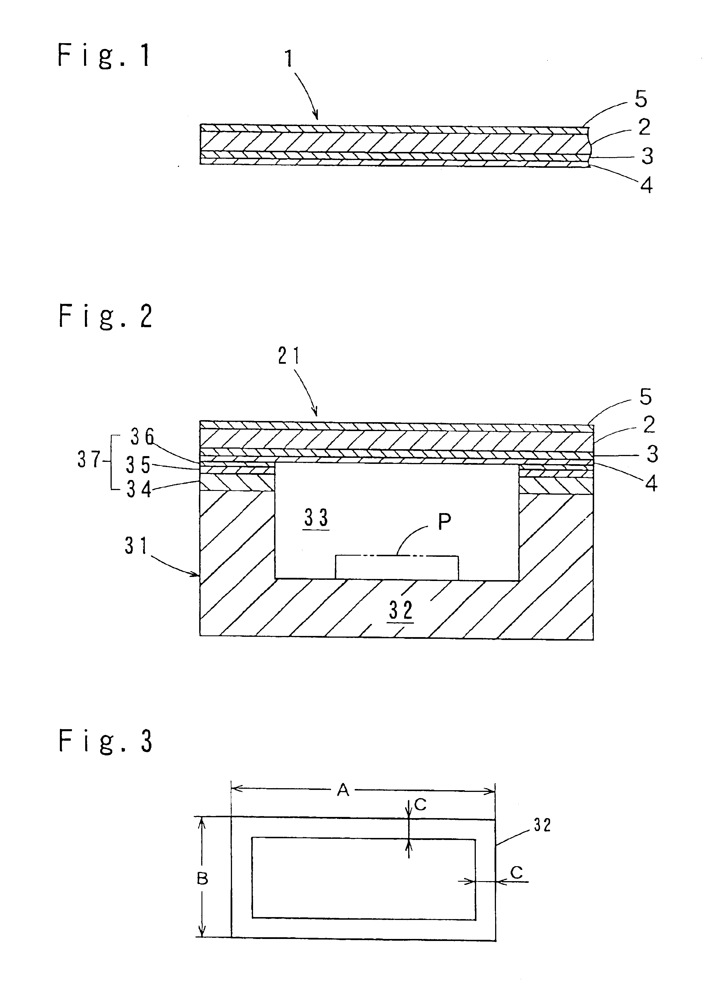
The present invention relates to a lid material for electronic component packages that can be fuse-bonded to the case around an opening. The lid material is made up of a base layer, an intermediate metal layer, and a brazing material layer. The intermediate metal layer is made of a low thermal expansion metal and a low proof stress metal, which ensures excellent brazing workability and prevents thermal stress and breakage of the case. The brazing material layer is made of a silver brazing alloy and is press-bonded onto the intermediate metal layer. The lid material is excellent in stampability and productivity. The invention also provides a method for producing the lid material.

Problems solved by technology

The thermal stress causes cracks in the walls, resulting in the problem of reduced hermeticity.
This problem is associated with not only the seam welding but also the electron beam welding.
However, a sufficient effect cannot be provided for prevention of the breakage of the thin walls of the case having a reduced size.
This results in very poor brazing workability, thereby leading to lower package productivity.
Therefore, where a brazing material such as a silver brazing alloy having an inferior cold press-bonding property is employed instead of the soldering material, a bonding strength between the Ni-based metal layer and the brazing material layer is problematic.

Method used


Image

  • Package for electronic parts, lid thereof, material for the lid and method for producing the lid material
  • Package for electronic parts, lid thereof, material for the lid and method for producing the lid material

Examples


examples

[0049]Samples of lid materials of four-layer structure as shown in FIG. 1 were each produced in the following manner. A base sheet of a Fe—29 mass % Ni—17 mass % Co alloy having a width of 20 mm and a thickness of 1100 μm was prepared as a material for a base layer 2, and a nickel sheet of pure Ni having a width of 20 mm and a thickness of 100 μm was prepared as a material for a nickel-based metal layer 5. Further, a copper sheet of oxygen-free copper (Cu: 99.95 mass %, O: 0.0006 mass %) having a width of 20 mm and a thickness of 600 μm was prepared as a material for an intermediate metal layer 3. The nickel sheet was stacked on one surface of the base sheet, and the copper sheet was stacked on the other surface of the base sheet. Then, the resulting stack was cold-rolled at a rolling reduction ratio of 60% to provide a copper layer laminate in which the respective adjacent material sheets are press-bonded. The copper layer laminate was diffusion-annealed in an annealing oven at 100...


PUM

PropertyMeasurementUnit
thicknessaaaaaaaaaa
thicknessaaaaaaaaaa
temperatureaaaaaaaaaa

Abstract

A lid material (1) according to the present invention comprises: a base layer (2) composed of a low thermal expansion metal; an intermediate metal layer (3) provided on one surface of the base layer (2) and composed of a low proof stress metal having a proof stress of not greater than 110 N / mm2; and a brazing material layer (4) provided on the intermediate metal layer (3) and composed of a silver brazing alloy mainly comprising silver. The intermediate metal layer (3) and the brazing material layer (4) are press- and diffusion-bonded to each other, and the brazing material layer (4) has a blistered area ratio of not greater than 0.5% as observed on an outer surface of the brazing material layer. The low proof stress metal is preferably oxygen-free copper. A lid produced from the lid material (1) exhibits an excellent bonding property when the lid is brazed to a case mainly composed of a ceramic material for an electronic component package. Further, the lid suppresses the breakage of the case, and ensures excellent brazing workability.

Description

BACKGROUND OF THE INVENTION[0001]1. Field of the Invention[0002]The present invention relates to an electronic component package having a case for housing an electronic component and a lid sealing an opening of the case, to a lid for the package, and a lid material for the lid.[0003]2. Description of the Related Art[0004]Packages for housing various electronic components such as semiconductor devices and piezoelectric vibrators comprise a case having an opening through which an electronic component housing cavity defined therein opens in an upper surface thereof, and a lid brazed to a portion of the case around the opening to close the opening of the case for sealing the cavity, as disclosed in Japanese Unexamined Patent Publication No. 2000-3973 (Patent Document 1).[0005]The case is mainly composed of a ceramic material such as alumina or aluminum nitride. On the other hand, the lid comprises a base layer composed of a low thermal expansion metal such as a Fe—29% Ni—17% Co alloy (t...

Claims


Application Information

Patent Timeline
Patent Type & Authority Patents(United States)
IPC IPC(8): H01L23/02H01L23/10
CPCB32B15/018H01L23/10H01L2924/01079H01L2924/0002H01L2924/00H01L2924/16195H01L23/02
Inventor SHIOMI, KAZUHIROISHIO, MASAAKI
Owner DAISHINKU CORP
Learn More