Three-level power converter and power unit thereof

a power converter and power unit technology, applied in power conversion systems, ac-dc conversion, electrical apparatus, etc., can solve the problems of increasing manufacturing costs, damage to controllable semiconductor devices, and the price and performance of high-power igbt is not as good as that of normal igbt, so as to reduce stray inductance

Active Publication Date: 2016-03-31
DELTA ELECTRONICS INC
View PDF11 Cites 18 Cited by
  • Summary
  • Abstract
  • Description
  • Claims
  • Application Information

AI Technical Summary

Benefits of technology

[0011]The present disclosure is to provide a power unit which may reduce stray inductance, and a three-level power converter having the power unit of the present disclosure.

Problems solved by technology

Further, the price and performance of high power IGBT is not as good as that of normal IGBT.
It may be seen that in three-level power converter, when the ON / OFF state of the controllable power semiconductor switch device is switched, the voltage induced by stray inductance will increase electrical stress of the controllable power semiconductor switch device, which affects the performance of the controllable semiconductor device, and may damage the controllable semiconductor device, and improves the requirement for performance of the controllable semiconductor device, thus increases manufacturing cost.
However, when the controllable power semiconductor switch device Sa is turned on next time, the energy of the energy storage element on the snubber circuits will be released through the controllable power semiconductor switch device Sa, thus generating additional turn on consumption for the controllable power semiconductor switch device Sa, which degrades the dynamic performance of the controllable power semiconductor switch device.
Further, the snubber circuit will go against the promotion of the power density and cost reduction.

Method used


Image

  • Three-level power converter and power unit thereof
  • Three-level power converter and power unit thereof
  • Three-level power converter and power unit thereof

Examples


embodiment 1

for a Power Unit

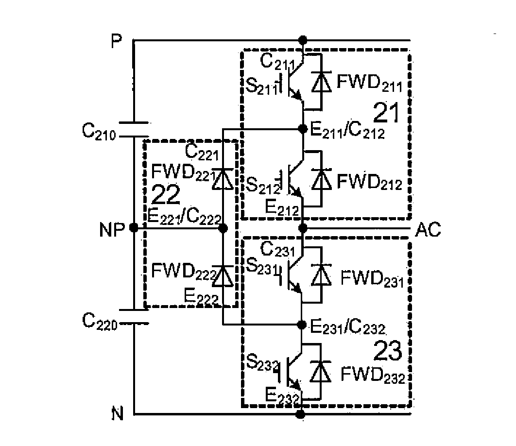
[0035]Referring to FIG. 4A and FIG. 4B, a power unit according to a first embodiment of the present disclosure comprises a power switch module 20 and a laminated busbar structure. The power unit further comprises a heat sink 24 on which the power switch module 20 is provided. The power switch module 20 comprises a first power semiconductor switch module 21, a clamping diode module 22 and a second power semiconductor switch module 23. The first power semiconductor switch module 21, the clamping diode module 22, and the second power semiconductor switch module 23 are provided on the heat sink 24.

[0036]The first power semiconductor switch module 21 comprises a first power semiconductor switch S211 and a second power semiconductor switch S212 connected with each other in series, a first fly-wheel diode FWD211 connected in parallel with the first power semiconductor switch S211, and a second fly-wheel diode FWD212 connected in parallel with the second power semiconductor ...

embodiment 2

for a Power Unit

[0083]Referring to FIG. 7, the second embodiment of the present disclosure is different from that in the first embodiment as described below.

[0084]The laminated busbar structure in the second embodiment is adapted to a power switch module 20 having three connection terminals, that is, the first power semiconductor switch module 21 of the power switch module 20 comprises a first terminal, a second terminal and a third terminal. The first end comprises only one first sub-terminal C211, and the second end comprises only one second sub-terminal E212 The clamping diode module 22 of the power switch module 20 comprises a first terminal, a second terminal and a third terminal. The first end comprises only one first sub-terminal C221, and the second end comprises only one second sub-terminal E222. The second power semiconductor switch module 23 of the power switch module 20 comprises a first terminal, a second terminal and a third terminal. The first terminal comprises only ...

embodiment 3

for a Power Unit

[0099]Referring to FIG. 10, the power unit P300 according to an embodiment of the present disclosure comprises a housing structure, a power switch module 20 in the housing structure, laminated busbar structure, positive bus capacitor bank and negative bus capacitor bank. The power switch module 20 is the one as mentioned before in the present disclosure. The first connection terminal 27 of the power switch module 20 connects to a positive bus input conductor B330, the second connection terminal 28 connects to a negative bus input conductor B340, the third connection terminal 29 connects to a neutral point bus input conductor B350, and the fourth connection terminal 210 connects to an AC bus conductor B360.

[0100]The positive bus input conductor B330, the negative bus input conductor B340, the neutral point bus input conductor B350 and the AC bus conductor B360 fix to the housing structure respectively in an insulation circumstance.

Embodiment of the Three-Level Power C...


PUM


Abstract

Provided are a three-level power converter and a power unit thereof. The power unit includes a power switch module and a laminated busbar structure. The power switch module includes a first power semiconductor switch module and a clamping diode module, which have a first, second, and third terminal respectively. The laminated busbar structure includes a third, second, and first busbar layer laminated on the power switch module. The third busbar layer includes a first sub-busbar connecting to the first terminal of the first power semiconductor switch module, a second sub-busbar connecting to the third terminal of the first power semiconductor switch module and the first terminal of the clamping diode module, a third sub-busbar connecting to the second terminal of the clamping diode module and the third terminal of the second power semiconductor switch module, and a fourth sub-busbar connecting to the second terminal of the second power semiconductor switch module.

Description

CROSS REFERENCE TO RELATED APPLICATIONS[0001]This application claims the priority to and the benefit of Chinese Patent Application No. 201410503410.8, filed Sep. 26, 2014 and entitled “three-level power converter and power unit thereof,” which is incorporated herein by reference in its entirety.TECHNICAL FIELD[0002]The present disclosure relates to a three-level power converter and power unit thereof.DESCRIPTION OF PRIOR ART[0003]FIG. 1 illustrates a circuit topology schematic view for a power unit of a three-level power converter. S1, S2, S3 and S4 represent controllable power semiconductor switch device. FWD1, FWD2, FWD3, and FWD4 represent fly-wheel diode. D1 and D2 represent clamping diode. C1 and C2 represent dc-link capacitor. When the power unit works normally the voltage of the dc-link capacitor C1 is defined to V2, and the voltage of the dc-link capacitor C2 is defined to V2. That is, the maximum steady-state voltage withstood by S1, S2, S3 and S4, FWD1, FWD2, FWD3, FWD4, D...

Claims


Application Information

Patent Timeline
Patent Type & Authority Applications(United States)
IPC IPC(8): H02M7/797
CPCH02M7/797H02M7/487
Inventor LI, YANZHONG, QINGLONGWEN, SENLINHU, GUANGCHENG
Owner DELTA ELECTRONICS INC
Why Eureka
Try Eureka